Blog
Recent Posts
SAE J1939 Address Management Messages (Address Claim PGNs)
Posted by on
The following is an excerpt from A Comprehensible Guide To J1939 by Wilfried Voss.
According to SAE J1939/81, network management procedures are used to “collectively manage the network”.
While other higher layer protocols based on CAN Bus do not support dynamic node address assignments per default, the SAE J1939 standard provides yet another ingeniously designed feature to uniquely identify ECUs and their primary function.
The CAN standard in itself does not support node (ECU) addresses, only message IDs, where one node may manage multiple messages. However, the message ID must be hard-coded in the application program.
The SAE J1939 network management messages have the same characteristics as all other J1939 messages. These messages are:

- In case no address has been claimed as of yet the source address could be set to 254.
- The commanded address, since it is longer than 8 bytes, is sent using the Transport Protocol as described in chapter Transport Protocol.
Request For Address Claimed
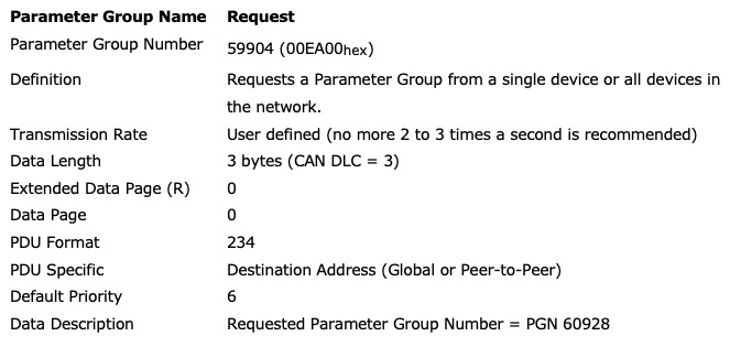
The Request for Address Claimed message (PGN 59904) is identical to the Request message type as described in SAE J1939/21 and chapter Parameter Group Numbers in this book.

The Request for Address Claimed message is used to request the sending of an Address Claimed message from either a particular node in the network or from all nodes (use of global destination address = 255). The Address Claimed message (as described in the following chapter) will provide the requested information, i.e. address and NAME of the responding node(s).
The purpose of sending such a request may be for several reasons, for instance:
- A node is checking whether or not it can claim a certain address.
- A node is checking for the existence of another node (Controller Application) with a certain function.
The response to a Request for Address Claimed message can be multiple:
- Any addressed node that has already claimed an address will respond with an Address Claimed message.
- Any addressed node that was unable to claim an address will respond with a Cannot Claim Address message.
- Any addressed node that has not yet claimed an address should do so by responding with their own Address Claimed message where the source address is set to NULL (254).
- A node sending the Request for Address Claimed message should respond to its own request in case the global destination address (255) was used.
Address Claimed / Cannot Claim
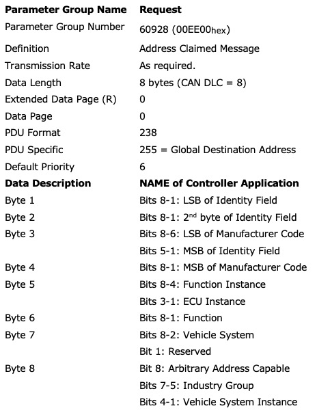
The Address Claimed message is used either, as the name indicates, to claim a message or to respond to a Request for Address Claimed message.
The following rules apply:
- The Address Claimed message, for the purpose of claiming an address, should always be addressed to the global address (255).
- The Address Claimed message, for the purpose of claiming an address, should be sent during the initialization of the network or as soon as the node is connecting to a running network.
- As soon as a node has successfully claimed an address, it may begin with regular network activities, i.e. sending messages or responding to messages.
- If a node (Controller Application) receives an Address Claimed message it should first compare the claimed address with its own. If the addresses are identical, the node should compare its own NAME to the NAME of the claiming node. In case its own NAME has a higher priority (lower numeric value) it will then transmit an Address Claimed message containing its NAME and address. If its own NAME is of a lower priority the node, depending on its capabilities, should either send a Cannot Claim Address message or claim another address.
- In case a node loses its address through the previously described procedure and was also in the process of sending a Transport Protocol message (see chapter Transport Protocol Functions) it should cease the transmission immediately, however, without sending a Transport Protocol Abort message. The receiver of the Transport Protocol message will detect the interruption through the corresponding timeout process.

The Cannot Claim Address message has the same format as the Address Claimed message, but it uses the NULL address (254) as the source address.
The following rules apply for the Cannot Claim Address message:
- As the name implies, a node without arbitrary addressing capabilities will send a Cannot Claim Address message when it is unable to claim the preferred address.
- A node with arbitrary addressing capabilities will send a Cannot Claim Address message when no addresses are available in the network.
- If the Cannot Claim Address message is a response to a Request for Address Claimed message, the node should apply a “pseudo-random” delay of 0 to 153 ms should be applied before sending the response. This will help prevent the possibility of a bus error, which will occur when two nodes send the same message with identical message ID.
Note: SAE J1939/81 is concerned that the occurrence of such an error condition will consume “a large number of bit times on the bus”. However, the time for transmitting a CAN Bus message with a 29-Bit ID followed by an error frame will be well under 1 ms.
SAE J1939 ECU Simulator Board With USB Port
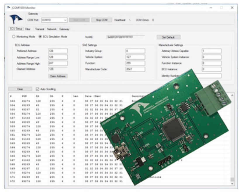
The jCOM.J1939.USB gateway board is a high-performance, low-latency vehicle network adapter for SAE J1939 applications. It allows any host device with a USB COM port to monitor SAE J1939 data traffic and communicate with the SAE J1939 vehicle network.
The board supports the full SAE J1939 protocol according to J1939/81 Network Management (Address Claiming) and J1939/21 Transport Protocol (TP). It is also supported by an extensive programming interface for Windows and Linux/Ubuntu applications, including full C/C++/C# source code for short time-to-market developments.
The strength of the board lies in the fact that the entire SAE J1939 protocol, including all timing requirements, is stored on-chip, thus taking the burden off the main system. The board uses a USB COM port to communicate with the main system, i.e. all data transfer is handled through a standard COM port access.
The communication protocol between the board and the main system is well documented and thus allows a porting to any computer system with a USB connection. Working source code libraries exist for Windows (C# under Visual Studio 2012/2013), Linux and its derivatives (C++ using Code::Blocks), and Raspberry Pi (C using the standard gcc compiler).
SAE J1939 Starter Kit And Network Simulator - Quick Start
Our jCOM.J1939 Starter Kit And Network Simulator is designed to allow the experienced engineer as well as the beginner experimenting with SAE J1939 data communication without the need of connecting to a real-world J1939 network, i.e., a diesel engine. To establish a network, you need at least two nodes, and that fact applies especially to the CAN Bus [...]
SAE J1939 Simulator Generates Frequently Used SAE J1939 Signals (PGNs) For Diesel Engines
Our SAE J1939 ECU Simulator Board With USB Port allows any host device (e.g., PC) with a USB COM port to monitor SAE J1939 data traffic and communicate with the SAE J1939 vehicle network, which makes it also suitable to simulate SAE J1939 data traffic. The simulation of SAE J1939 signals (i.e., PGNs) is a valuable [...]
SAE J1939 vs. CAN Bus - Physical Layer And Higher Layer Protocol (HLP)
To answer the fundamental question upfront: SAE J1939 is a higher-layer protocol (i.e., an add-on software) that uses the CAN Bus technology as a physical layer. In addition to the standard CAN Bus capabilities, SAE J1939 supports node addresses, and it can deliver data frames longer than 8 bytes (in fact, up to 1785 bytes). However, [...]
Low-Cost Do-It-Yourself CAN Bus To WiFi, Bluetooth, BLE, USB, RS485 Gateway Based On Raspberry Pi Zero
In the following, I will discuss a do-it-yourself project utilizing the Raspberry Pi Zero in combination with the CAN Bus Plus RS485 HAT. The combination of serial and wireless ports provided by this system allows the development of a great number of gateway applications. Overall, this small-size hardware includes connections such as CAN Bus, RS485, [...]
Electronic Logging Device Concept: Small Form-Factor ELD Based On Raspberry Pi With CAN Bus Port And GSM/GPRS/GNSS Support
An electronic logging device (ELD) is an electronic hardware that is attached to a commercial motor vehicle engine to record driving hours. The driving hours of commercial drivers (truck and bus drivers) are regulated by a set of rules known as the hours of service (HOS). The Commercial Vehicle Driver Hours of Service Regulations vary in Canada [...]
Easy Integration Of CANopen Or SAE J1939 Protocol Stack Into Any Embedded System With Serial Input
The simple assumption behind the statement of easy integration of a CANopen or SAE J1939 protocol stack is that virtually every embedded system (and even other industrial controls such as PLCs) do have a serial port of some sort, mostly UART, RS232, or USB. "Easy" also implies that you don't have to go through major [...]
Controller Area Network (CAN Bus) - Message Broadcasting
The following is an excerpt from A Comprehensible Controller Area Network by Wilfried Voss. The broadcasting of messages in a CAN Bus network is based on a producer-consumer principle. One node, when sending a message, will be the producer while all other nodes are the consumers. All nodes in a CAN Bus network receive the same message at the [...]
SAE J1939 Address Management Messages - Request For Address Claimed And Address Claimed
The following is an excerpt from A Comprehensible Guide To J1939 by Wilfried Voss. According to SAE J1939/81 network management procedures are used to “collectively manage the network”.In all consequence the network management is all about the Address Claim procedure and this procedure utilizes three messages and their PGNs:Request Message (PGN 59904)Address Claimed / Cannot Claim (PGN 60928)Cannot Claim Source Address [...]
Dual CAN FD Interface Board With Real Time Clock For Raspberry Pi
CAN FD (CAN with Flexible Data-Rate) is an extension to the original CAN Bus (Classic CAN) protocol specified in ISO 11898-1. CAN FD was created to provide gains in bandwidth within automotive and industrial networks. The CAN FD protocol has moved application software closer to "real time" through the reducing delays between instruction and transfer of [...]
 Loading... Please wait...


