 Loading... Please wait...
- Home
- Documentation
- SAE J1939 Starter Kit - Monitor, Record, Analyze, and Simulate SAE J1939 Data Traffic
SAE J1939 Starter Kit - Monitor, Record, Analyze, and Simulate SAE J1939 Data Traffic

The SAE J1939 Starter Kit is the perfect learning tool to familiarize yourself with the SAE J1939 protocol, especially in combination with our book, A Comprehensible Guide to J1939. The combination of simulation hardware and readable SAE J1939 reference provides a pleasing contrast to working through the dry SAE J1939 Standards Collection (standards are written for reference without educational aspects or intentions.)
 The SAE J1939 Starter Kit and Network Simulator allows the experienced engineer and the beginner to experiment with SAE J1939 data communication without the need to connect to a real-world J1939 network, i.e., a diesel engine.
It may sound obvious, but in order to establish a network, you need at least two nodes. That fact applies especially to CAN/SAE J1939, where the CAN Bus controller will shut down after transmitting data without receiving a response. For that reason, the SAE J1939 Starter Kit and Network Simulator consists of two SAE J1939 nodes, namely our JCOM.J1939.USB-B, an SAE J1939 ECU Simulator Board with USB Port.
The JCOM.J1939.USB-B gateway board is a high-performance, low-latency vehicle network adapter for SAE J1939 applications. The board supports the full SAE J1939 protocol according to J1939/81 Network Management (Address Claiming) and J1939/21 Transport Protocol (TP).
For more information on the JCOM.J1939.USB-B gateway board, see:

The idea behind the network simulator is to connect both nodes to the same PC (two PCs will do, too) and running two instances of our JCOM1939 Monitor Software after assigning the boards to their corresponding COM port.
The JCOM1939 Monitor Software is the perfect tool to monitor, analyze, and simulate SAE J1939 data traffic. This comprehensive and easy-to-use, easy-to-understand Windows software displays not only SAE J1939 data traffic; it also allows to scan the network, simulate an ECU (incl. full node address negotiation features), respond to data requests, and more.
For more information on the JCOM1939 Monitor Software, see:
For an overview of SAE J1939 and its hardware layer, the CAN Bus technology, see:
Quick Start Reference
The following is intended to present a quick reference for the newcomer to succeed smoothly.
First of all, it is vital to notice that this starter kit is all you need to simulate an SAE J1939 vehicle network. No additional hardware is required, but you can still connect the Starter Kit to any external network for monitoring and communication purposes.
Please ensure that both boards are connected to a Windows PC per the provided USB cable. The USB port also acts as the power supply, and the network will not be complete unless both nodes are working. As soon as power is applied, you should see LED2 (LED for USB Activity) blinking at a one-second frequency. This is the so-called heartbeat, indicating that the board is "alive."
In the Windows Device Manager, check the assigned COM ports:
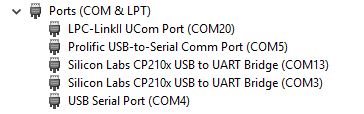
The JCOM.J1939.USB device shows up as "Silicon Labs CP210x USB to UART Bridge," as displayed in the above image. In this case, the boards show up as COM3 and COM13. These settings will most probably differ on your computer, but COM3 is the default port, and one of the boards will claim it when available.
As a next step, start the jCOMJ1939 Monitor software; for more information on download and installation, see JCOM1939 Monitor Pro - SAE J1939 Data Monitor, Recorder, Simulator.
To open the first instance of the software, simply double-click on the JCOM1939 Monitor Pro icon. To open the second instance, right-click on the icon and select Open.
Each instance needs to be connected to the corresponding COM port. In the following example, we assigned COM3 as the COM port for data transmission, while COM13 acts as the receiver. Click on Start COM to initiate communication with the board.
We have also created a test file (SAEJ1939StarterKit-Test.jcom) that assigns a few sample PGNs for transmission. Please download the file and load it through the JCOMJ1939 Monitor software.
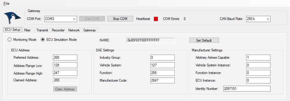
After loading the file, click ECU Simulation Mode, then click on Claim Address, and you should see a data flow immediately.
Note: An SAE J1939 node (ECU) can only transmit data after it claimed a valid node address.
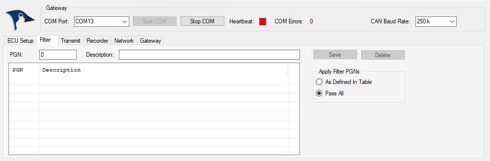
Now open a second instance of the JCOMJ1939 Monitor software and assign the second COM port (in our example, COM13). Again, click on Start COM to initiate communication with the board.
In the Filter section (see below), select Pass All, and you should see the same data stream.
Using this example, one node transmits SAE J1939 data, while the other receives it. However, you can even create examples where both nodes receive and transmit, and you can create message requests and their responses.
Bi-Directional Data Transmission
Working with the Starter Kit becomes, of course, more interesting when we initiate a bidirectional data transfer, i.e., both SAE J1939 nodes transmit and receive. There are two essential rules that we need to follow to comply with the SAE J1939 and CAN Bus protocol:
- 1. The SAE J1939 modules must use different node addresses.
- 2. The SAE J1939 modules cannot transmit the same PGNs.
Note: Operating two nodes with the same node address and/or transmitting identical PGNs will result in unpredictable network conditions.
Going back to our previous sample setup file (SAEJ1939StarterKit-Test.jcom), we see that it assigns a node address of 200 (see the image in the previous paragraph) and transmits four PGNs: 65281, 65285, 65290, and 65299. These PGNs were chosen randomly and are not associated with any vehicle data.

In the following, we will use the setup for one node. The COM port setting is of no significance here, meaning you can freely choose one or the other board.
For the second node, we will use node address 128 and two sample PGNs, 65282 and 65283, as shown in the following image:

This setup is stored in our file SAEJ1939StarterKit-Node2.jcom file.
After loading the files to their corresponding nodes, click ECU Simulation Mode, then click on Claim Address, and you should see a data flow immediately.
In the Filter section, select Pass All, and you should see the full data stream, transmitted and received.
The image below shows the data traffic on the second node:

Address Claim Example
Now, let’s make things a bit more interesting and assign the same node address to both modules. We are still using the same setup (jcom) files for both nodes but change the node address in the ECU Setup section from 200 to 128.
Please assure you have both nodes set back to Monitoring Mode, then change the node address.

Now, both modules use the same node address (128), but they also use the same NAME information, which is not allowed, since this may result in message collisions.
Note: The SAE J1939 protocol uses the NAME information for the Address Claim procedure. Nodes with lower NAME value take precedence over higher NAMEs.
In order to change the NAME, we have set the ECU Instance from 0 to 1. The new situation is as follows:
Node Address NAME
1 128 0x80FEFF01FFFFFFFF
2 128 0x80FEFF00FFFFFFFF
First, let’s claim the address for node 1 (formerly 200, now 128) by clicking on the Claim Address command button. This will also initiate the data transfer. The claimed address is still 128.
Secondly, claim the same address for the second node. Since node 2 comes with a lower name, it will claim node address 128, while node 1 switches to the next available node address of 129.

For more information on the SAE J1939 Address Claim procedure, see:
- Guide To SAE J1939 - Address Claiming Procedure Overview...
- SAE J1939 Address Management Messages (Address Claim PGNs)...