Blog
Recent Posts
SAE J1939 Technology for Agricultural Applications
Posted by on
 The rapid advancement of technology in the agricultural sector has led to the integration of sophisticated systems to enhance efficiency, productivity, and sustainability. One such innovation is the use of the SAE J1939 protocol, a communication standard widely utilized in the field of commercial vehicles and machinery. In agricultural applications, this protocol plays a pivotal role in enabling interoperability, improving machine diagnostics, and enhancing data-driven decision-making.
Understanding SAE J1939
SAE J1939 is a high-level communication protocol developed by the Society of Automotive Engineers (SAE). It operates over the Controller Area Network (CAN) bus and facilitates the exchange of data between electronic control units (ECUs) in heavy-duty vehicles, including tractors, harvesters, and other agricultural equipment. The protocol provides a standardized framework for communication, ensuring that different devices can seamlessly interact with one another, regardless of the manufacturer.
The core components of SAE J1939 include:
- Message Identifier (PGN): Each message transmitted over the CAN bus is identified by a Parameter Group Number (PGN), which defines the data type and its purpose.
- Data Field: The content of the message, which may include parameters such as engine speed, fuel consumption, or hydraulic pressure.
- Transport Protocol: Mechanisms for transmitting large data packets beyond the 8-byte CAN frame limit.
Key Benefits in Agriculture
- Interoperability Agricultural machinery from different manufacturers often needs to work together in a single operation. SAE J1939 ensures that ECUs in various machines, such as tractors and implements, can communicate effectively. This interoperability reduces downtime and simplifies the integration of new equipment.
- Enhanced Diagnostics With the increasing complexity of agricultural machinery, efficient diagnostics are essential to minimize downtime and repair costs. SAE J1939 provides real-time access to diagnostic trouble codes (DTCs) and operational data, enabling technicians to quickly identify and resolve issues.
- Data Collection and Analysis Modern farming relies heavily on data-driven decision-making. SAE J1939 allows the collection of critical operational data, such as engine performance, fuel efficiency, and implementation usage. This data can be analyzed to optimize machinery performance, reduce fuel consumption, and improve overall farm management.
- Improved Safety and Control The protocol enables advanced safety features, such as automatic shut-off and precise control of machinery operations. For example, it can facilitate the synchronization of speed and position between a tractor and a trailer, reducing the risk of accidents and improving efficiency.
Applications in Precision Agriculture
Precision agriculture is a farming approach that utilizes technology to optimize resource use and maximize crop yields. SAE J1939 plays a critical role in this domain by:
- Connecting Sensors and Actuators: It allows seamless communication between sensors (e.g., soil moisture, GPS) and actuators (e.g., sprayers, seeders).
- Automated Machine Guidance: SAE J1939 supports the integration of GPS-based guidance systems, enabling automated steering and precise field operations.
- Variable Rate Technology (VRT): The protocol facilitates real-time data exchange, enabling machinery to adjust inputs like fertilizer or pesticide application based on field conditions.
Future Prospects
As the agricultural industry continues to embrace digitalization, the role of SAE J1939 is expected to grow. Emerging trends, such as the Internet of Things (IoT) and artificial intelligence (AI), will further enhance the capabilities of this protocol. For instance, cloud-based platforms could leverage SAE J1939 data to provide predictive maintenance insights and optimize fleet management.
Conclusion
SAE J1939 technology is a cornerstone of modern agricultural operations, providing a robust framework for communication and data exchange among machinery. Its benefits in terms of interoperability, diagnostics, data analysis, and safety make it indispensable for precision agriculture and other advanced farming practices. As technology evolves, SAE J1939 will continue to play a crucial role in driving agricultural innovation and sustainability.
SAE J1939 Starter Kit and Network Simulator
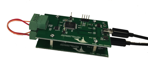
Our JCOM.J1939 Starter Kit and Network Simulator was designed to allow experienced engineers and beginners to experiment with SAE J1939 data communication without needing to connect to a real-world J1939 network, i.e., a diesel engine.
To establish a network, you need at least two nodes. This applies especially to CAN/J1939, where the CAN controller will shut down after transmitting data without receiving a response. Therefore, our jCOM.J1939 Starter Kit and Network Simulator consist of two J1939 nodes: our jCOM.J1939.USB, an SAE J1939 ECU Simulator Board with USB Port. More Information...
Improvements to our JCOM1939 Monitor & Simulation Software for Windows
Our SAE J1939 gateways are steadily gaining popularity, so we developed a dedicated website that focuses on the associated JCOM1939 Monitor Software for Windows. Since July of this year, we have added new features, some small and some significant improvements. With version 3.50.00, we have ceased support for older gateways, specifically those sold before 2022. The processors in [...]
NMEA 2000 Product Certification for Marine Applications
The NMEA 2000 product certification is a mark of reliability, ensuring quality and interoperability for NMEA 2000 networks. It guarantees that a device supports a mandatory set of protocol services and hardware requirements. Developers can carry out the certification themselves or be supported by engineers with experience in NMEA 2000 certification. NMEA 2000 is a protocol [...]
JCOM1939 Monitor Pro - SAE J1939 Data Monitoring, Recording
Our SAE J1939 to USB/Bluetooth gateway and the SAE J1939 Starter Kit are designed to work seamlessly with our JCOM1939 Monitor Pro Software for Windows, a free download. This combination is key to ensuring your purchased product's optimal performance and overall satisfaction. For your convenience, we have meticulously crafted a dedicated website. This one-stop hub houses [...]
Turn Your Smartphone into a Heavy-Duty Diagnostics Tool
Turn your smartphone into a user-friendly HD diagnostic tool. Download and sync via Bluetooth to the free Diesel Decoder smartphone app to view vital diagnostic and trip data. When your rig throws a fault code, the Diesel Decoder is your reliable companion. It removes the guesswork, guiding you to either clear the codes and continue your journey [...]
Literature on Maritime Electronics, Including NMEA 2000
Replacing Your Boat's Electrical System The electrical system on a boat is crucial for the operation of all manner of valuable and critical equipment, yet a simple failure or weakness can render these systems inoperable. In older boats, fatigued or damaged wiring can be problematic or even terminal, so Mike Westin shows how to replace a [...]
Display for Off-Road Vehicle Engines with J1939 interface
The EngineMonitorPlus is a display and control device with a CAN Bus interface designed specifically for use in off-road vehicle engines. It supports the most common messages (PGN, Parameter Group Number) of the SAE J1939 standard. Furthermore, it provides a simple configuration of displayed parameters, errors (DM1), and service messages, allowing the user to configure and [...]
Programming Electrac Linear Actuator - ACM, AFM Data Frames
This post represents an excerpt of Thomson Electrac HD Linear Actuator Motion Control per CAN Bus. The application note is available in eBook and Kindle format, and it includes a free downloadable source code. More Information... In this post, I am explaining the Actuator Control Message (ACM) and Actuator Feedback Message (AFM).Thomson Electrac Linear Actuator - ACM Design The [...]
SAE J1939 Display Units for Off-Highway Industrial Engines
The Enginemonitor displays by B-Plus are expansion tools, especially for industrial engines with SAE J1939 interfaces. They enable users to retrieve information from mobile machines and communicate commands directly. Thanks to their robust housings and protection level, the devices can operate directly in the cab and the outdoor area of mobile machines. Due to various device versions, the [...]
J1939 Protocol Stack Sketch for ESP32 Using the Arduino IDE
The ESP32 is a series of low-cost, low-power system-on-chip microcontrollers with integrated Wi-Fi and dual-mode Bluetooth. The ESP32 series employs a Tensilica Xtensa LX6 microprocessor in both dual-core and single-core variations and includes built-in antenna switches, RF balun, power amplifier, low-noise receive amplifier, filters, and power management modules. Furthermore, the processor provides the means to easily [...]
 Loading... Please wait...

