 Loading... Please wait...
Blog
Recent Posts
CAN Bus vs. CAN FD: When Is It Worth Upgrading? A Practical Guide for Embedded System Developers
Posted by on
 For more than three decades, Classical CAN (Controller Area Network) has been the workhorse of industrial automation, automotive electronics, agricultural machinery, marine systems, and countless embedded applications. It has earned a reputation for exceptional reliability, deterministic communication, and outstanding error detection.
Yet the demands placed on embedded networks continue to grow. Today's systems generate far more data than they did even a decade ago. Cameras, radar, high-resolution sensors, firmware updates, diagnostics, predictive maintenance, and over-the-air software deployment all require more bandwidth than Classical CAN was originally designed to handle.
This is where CAN FD (Flexible Data-Rate) enters the picture.
But does every CAN application need CAN FD? Should existing products be redesigned? Or is Classical CAN still the better choice for many applications?
The answer depends entirely on your application.
In this article, we'll examine the practical differences between Classical CAN and CAN FD, discuss when upgrading actually makes sense, and show how developers can experiment with both technologies using a single development platform.
Why Classical CAN Has Been So Successful
Since its introduction by Bosch in the 1980s, Classical CAN has become one of the most successful industrial communication protocols ever created.
Its strengths include:
-
Extremely reliable communication
-
Robust error detection and fault confinement
-
Deterministic arbitration
-
Low implementation cost
-
Excellent interoperability
-
Huge ecosystem of controllers, transceivers, analyzers, and software
Millions of vehicles and industrial systems continue to operate flawlessly using Classical CAN today.
If your network carries only sensor values, switch states, control commands, or modest amounts of process data, Classical CAN remains an excellent solution.
There is no technical reason to replace it simply because CAN FD exists.
The Limitations of Classical CAN
Technology evolves.
Modern embedded systems often require significantly higher data throughput than earlier generations.
Classical CAN has two fundamental limitations:
1. Maximum Payload Size
Each CAN frame carries a maximum of:
8 bytes
While sufficient for many control applications, eight bytes quickly become restrictive when transmitting:
-
Sensor arrays
-
Diagnostic records
-
Firmware blocks
-
GPS information
-
Configuration parameters
-
Measurement datasets
Large messages must be fragmented into multiple CAN frames.
2. Limited Data Rate
Classical CAN typically operates at:
-
125 kbit/s
-
250 kbit/s
-
500 kbit/s
-
1 Mbit/s (maximum)
While adequate for many networks, higher bus utilization increases latency and reduces available bandwidth for future expansion.
What Makes CAN FD Different?
CAN FD was specifically designed to overcome these limitations while maintaining compatibility with existing CAN concepts.
Two major improvements distinguish CAN FD.
Larger Data Payload
Instead of 8 bytes, CAN FD supports:
-
12 bytes
-
16 bytes
-
20 bytes
-
24 bytes
-
32 bytes
-
48 bytes
-
64 bytes
This eight-fold increase dramatically reduces protocol overhead.
For example:
Instead of transmitting eight Classical CAN frames, a single CAN FD frame may carry the same information.
That means:
-
fewer arbitration cycles
-
less bus traffic
-
lower processor overhead
-
improved efficiency
Faster Data Phase
CAN FD introduces two bit rates.
Arbitration Phase
Still operates at the traditional CAN bit rate.
This guarantees compatibility with the existing arbitration mechanism.
Data Phase
Once arbitration completes, the frame may switch to a much higher transmission speed.
Common values include:
-
2 Mbit/s
-
4 Mbit/s
-
5 Mbit/s
-
8 Mbit/s
This dramatically shortens transmission time for larger payloads.
Does CAN FD Replace Classical CAN?
No.
This is perhaps the biggest misconception.
CAN FD is not intended to replace every Classical CAN network.
Instead, it extends the CAN family for applications that genuinely benefit from:
-
larger payloads
-
increased throughput
-
lower latency
-
future scalability
Many industrial products shipping today continue to use Classical CAN because it fully satisfies their communication requirements.
When Should You Stay with Classical CAN?
Classical CAN remains the preferred choice if your application involves:
-
Industrial controllers
-
PLC communication
-
Engine control
-
Agricultural equipment
-
Marine electronics
-
Simple sensor networks
-
HVAC systems
-
Elevator controls
-
Robotics
-
Machine automation
particularly when:
-
messages are short
-
update rates are moderate
-
network utilization is low
In these situations, upgrading provides little practical benefit.
When Does CAN FD Become Worthwhile?
CAN FD starts to shine when your application requires significantly more bandwidth.
Examples include:
Advanced Diagnostics
Instead of sending dozens of small diagnostic frames, larger datasets fit into a handful of CAN FD messages.
Firmware Updates
Bootloaders benefit enormously from 64-byte payloads.
Fewer packets mean:
-
shorter update times
-
less protocol overhead
-
improved reliability
Data Logging
High-speed logging systems often collect:
-
temperatures
-
pressures
-
accelerometer data
-
GPS coordinates
-
battery information
Sending these measurements in larger CAN FD frames greatly improves efficiency.
Sensor Fusion
Modern embedded systems combine information from multiple sensors.
Rather than distributing data across many Classical CAN frames, CAN FD can package related measurements into a single message.
Gateway Applications
Gateways often aggregate traffic from multiple networks.
Larger payloads simplify message translation and reduce processing overhead.
Is Upgrading an Existing Product Worth It?
That depends on one question:
What problem are you trying to solve?
If your current system already:
-
meets timing requirements
-
has available bandwidth
-
operates reliably
then there may be little benefit in redesigning it.
However, if you are developing a new generation of your product, CAN FD provides valuable headroom for future expansion.
Many manufacturers now adopt CAN FD not because today's application demands it, but because tomorrow's likely will.
The Best Way to Learn CAN FD
One of the biggest challenges developers face is gaining hands-on experience without abandoning their existing CAN knowledge.
 A development board that supports both Classical CAN and CAN FD provides the ideal learning environment.
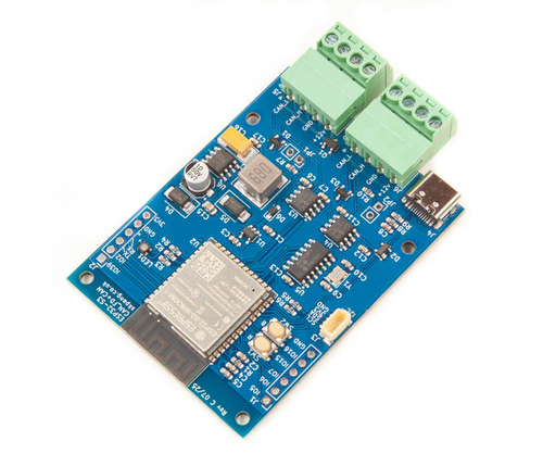
The ESP32S3 Board with CAN FD and Classical CAN Ports is an excellent example. Built around the ESP32-S3, it combines the microcontroller's native Classical CAN (TWAI) controller with a dedicated Microchip MCP2518FD CAN FD controller. This allows engineers to work with legacy CAN 2.0 networks and modern CAN FD networks on the same hardware platform. Additional features such as Wi-Fi, Bluetooth 5, native USB, generous Flash and PSRAM, and dual CAN interfaces make it suitable for gateways, data loggers, diagnostics tools, wireless monitoring systems, and protocol experimentation.
This architecture lets developers:
-
Compare Classical CAN and CAN FD side by side.
-
Measure bandwidth improvements with real applications.
-
Build gateways that bridge legacy and next-generation networks.
-
Evaluate software architectures before committing to a hardware redesign.
-
Develop firmware that supports both protocols.
Rather than forcing a binary choice, a dual-interface board provides a practical migration path while protecting your existing investment in Classical CAN.
Classical CAN and CAN FD Can Coexist
One of the strengths of modern CAN development is that migration doesn't have to happen all at once.
Many systems now use:
-
Classical CAN for existing ECUs
-
CAN FD for new subsystems
-
gateways connecting both worlds
This incremental strategy minimizes development risk while allowing new products to take advantage of CAN FD's capabilities.
Final Thoughts
CAN FD is an important evolution of one of the world's most successful fieldbus technologies. Its larger payloads and higher data rates solve real problems in data-intensive applications such as diagnostics, firmware updates, sensor fusion, and high-speed logging.
At the same time, Classical CAN remains the right solution for countless control systems where reliability, determinism, and simplicity matter more than raw bandwidth.
Rather than asking whether CAN FD is "better," the more useful question is whether it addresses the communication challenges of your application. If your network is approaching its bandwidth limits or your next product generation demands greater throughput, CAN FD is well worth considering. If not, Classical CAN may continue serving you reliably for many years.
For developers exploring both technologies, a platform that supports Classical CAN and CAN FD simultaneously offers the most practical path forward. It allows you to experiment, benchmark, and prototype with real hardware before deciding whether a migration is justified—making your next design decision based on engineering evidence rather than marketing claims.
 ESP32-C3/S3 Professional Handbook: Embedded Development with ESP-IDF, Arduino, Wi-Fi, Bluetooth LE, and Edge Intelligence
Have you ever wondered why some connected devices run for years on a single battery while others exhaust their power in just a few weeks? Are you trying to determine when a simple RISC-V core is sufficient—and when a dual-core, vector-accelerated architecture becomes indispensable? Have you found yourself bouncing between datasheets, forum posts, application notes, and scattered tutorials, wishing someone would finally explain how all the pieces fit together in a real production environment?
What if one comprehensive resource could answer those questions with the depth and clarity expected by professional engineers?
This book is written for embedded developers, product architects, and system designers who want to build connected devices that not only work in the lab but also survive certification testing, manufacturing, security audits, and years of reliable field operation. It tackles the same questions engineers face every day. How do memory maps, caches, DMA engines, and PSRAM interact under heavy workloads? What really happens during secure boot, flash encryption, and over-the-air (OTA) firmware updates? How should FreeRTOS tasks be partitioned across multiple cores for maximum performance? When do Wi-Fi and Bluetooth stacks become system bottlenecks, and how can they be optimized? How do you design for ultra-low power consumption, long battery life, and regulatory compliance from the very first schematic?
Rather than presenting these topics as isolated features, the book explains how they interact as part of a complete embedded system, providing the practical insight needed to design products that are robust, scalable, and ready for production. More information...
How to Build a CAN Bus Prototype Before Designing Your PCB
Modern embedded systems rarely begin with a custom PCB. In fact, the fastest and often the most successful development projects start on inexpensive development hardware that allows engineers to validate concepts, write firmware, and test communication long before the first schematic is finalized. When developing CAN Bus and SAE J1939 applications, I have found that the [...]
Why Embedded Engineers Need Raspberry Pi for CAN Bus Development
The Raspberry Pi has earned its reputation as one of the most versatile embedded computing platforms ever created. Originally introduced as an educational computer, it has evolved into a serious engineering tool used for industrial automation, robotics, automotive development, data acquisition, and IoT applications. For engineers working with CAN Bus and CAN FD networks, adding [...]
Understanding CAN Bus Error Frames: A Practical Guide to Diagnosing CAN Network Problems
When you first connect a new CAN Bus network, everything usually works perfectly—until it doesn't. Your firmware transmits messages, but nothing appears on the network. Your CAN controller reports transmit errors. Suddenly, the node enters Error Passive mode, and eventually Bus Off. Your analyzer may even display Error Frames, but it rarely explains why they occurred. If [...]
ESP32 CAN Bus Projects: Practical Wi-Fi Applications for Embedded Systems
The convergence of wireless networking and CAN Bus technology has fundamentally changed how engineers design embedded systems. For years, CAN Bus networks operated as isolated, wired communication systems found in vehicles, industrial equipment, agricultural machinery, and marine electronics. While they excel at reliable real-time communication, accessing data often required a physical connection through a CAN [...]
Why Professional Engineers Still Use the Arduino IDE in 2026
A recent Facebook comment caught my attention: "Who's using Arduino IDE in 2026?" At first, I dismissed it as another attempt to provoke a reaction. But the more I thought about it, the more I realized that it reflects a common misconception. Many engineers still associate the Arduino IDE exclusively with hobbyists building blinking LEDs and garage [...]
Why Teensy Is One of the Best Microcontrollers for CAN Bus Applications
When engineers begin working with Controller Area Network (CAN) systems, one of the first questions is usually, "Which microcontroller should I use?" The answer depends on the application, but one platform consistently stands out for its combination of performance, flexibility, and ease of development: Teensy. Originally developed by PJRC, the Teensy family has earned an excellent [...]
Building High-Speed Data Loggers with Teensy: From CAN Bus to Connected IoT Systems
Data logging has evolved far beyond simply recording CAN messages to a memory card. Today's engineers expect real-time visualization, multi-channel data acquisition, remote connectivity, cloud integration, and support for modern protocols such as CAN FD—all while maintaining deterministic performance and low latency. If you are designing a professional-grade data logger, the choice of hardware platform can [...]
Arduino Due Dual CAN Bus Development Platform for Rapid CAN Bus and SAE J1939 Prototyping
One of the biggest obstacles in CAN bus development is not understanding the CAN protocol itself—it is finding a development platform that lets you move from an idea to a working prototype without spending weeks configuring hardware, writing low-level drivers, or debugging interface electronics. Whether you are developing an automotive controller, an industrial CAN node, an [...]
Developing SAE J1939 Applications with ARD1939 and Copperhill Technologies Hardware
One of the challenges of developing SAE J1939 applications is finding a protocol stack that is both affordable and flexible enough for prototyping, education, and custom embedded projects. To address this need, we developed ARD1939, a portable C++ SAE J1939 protocol stack that serves as the software foundation for many of our development projects and examples. Originally [...]