 Loading... Please wait...
Blog
Recent Posts
CAN Bus Development with ESP32-WROOM32 Development Board
Posted by on
This post will demonstrate how to add a CAN Bus port to the ESP32-WROOM32 development board, i.e., regarding hardware and software.

As a matter of fact, we already offer a hardware utilizing the ESP32 processor and an onboard CAN Bus transceiver as shown in the image to the left.
The ESP32 WiFi, Bluetooth Classic, BLE, CAN Bus Module comes with an onboard ESP32 WROOM-32 WiFi, Bluetooth Classic, BLE Module, and a CAN Bus port with a transceiver. Also, onboard is an RGB LED, IO pins on a 0.1" pad.
The programming is accomplished through the popular Arduino IDE connected to the USB-to-Serial converter with USB-C connector, automatic bootloader and reset.
However, if you don’t need the supported 12 VDC power connection and extended temperature range (specifically suited for automotive and industrial applications) but are satisfied with the power supplied per USB port, you may prefer the lower-priced application as described here.
For this project we are using:
- ESP32-WROOM-32D Bluetooth, BLE, And WIFI Development Board with PCB Antenna...
- CAN Bus Mini Breakout Board...
The ESP32 is a low-cost, low-power system-on-chip microcontrollers with integrated Wi-Fi and dual-mode Bluetooth. It employs a Tensilica Xtensa LX6 microprocessor in dual-core and single-core variations and includes built-in antenna switches, RF balun, power amplifier, low-noise receive amplifier, filters, and power management modules. It is a successor to the ESP8266 SoC.
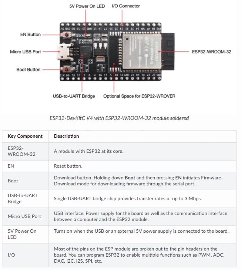
The ESP32 DevKit Board contains the ESP-WROOM-32 as the main module and some additional hardware to easily program ESP32 and connect with the GPIO Pins.
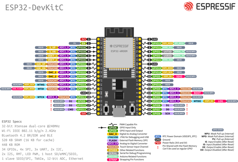
ESP32 Features
- Single or Dual-Core 32-bit LX6 Microprocessor with clock frequency up to 240 MHz.
- 520 KB of SRAM, 448 KB of ROM and 16 KB of RTC SRAM.
- Supports 802.11 b/g/n Wi-Fi connectivity with speeds up to 150 Mbps.
- Support for both Classic Bluetooth v4.2 and BLE specifications.
- 34 Programmable GPIOs.
- Up to 18 channels of 12-bit SAR ADC and 2 channels of 8-bit DAC
- Serial Connectivity include 4 x SPI, 2 x I2C, 2 x I2S, 3 x UART.
- Ethernet MAC for physical LAN Communication (requires external PHY).
- 1 Host controller for SD/SDIO/MMC and 1 Slave controller for SDIO/SPI.
- Motor PWM and up to 16-channels of LED PWM.
- Secure Boot and Flash Encryption.
- Cryptographic Hardware Acceleration for AES, Hash (SHA-2), RSA, ECC and RNG.
ESP32 Board Components
- ESP-WROOM-32 Module
- Two rows of IO Pins (with 15 pins on each side)
- CP2012 USB – UART Bridge IC
- Micro–USB Connector (for power and programming)
- AMS1117 3.3V Regulator IC
- Enable Button (for Reset)
- Boot Button (for flashing)
- Power LED (Red)
- Some passive components
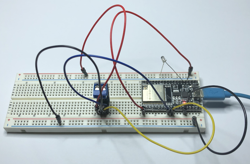
CAN Bus Connection
The ESP32 integrates a CAN Bus controller compatible with the NXP SJA1000, making it CAN 2.0B specification compliant.
As with the SJA1000, the ESP32 CAN Bus controller provides only the data link layer and the physical layer signaling sublayer. Therefore, an external transceiver module is required, which converts the ESP32's CAN-RX and CAN-TX signals into CAN_H and CAN_L bus signals. The transceiver, such as the MCP2551 or SN65HVD23X, provides compatibility with ISO 11898-2.
Note: The SJA1000 does not support CAN-FD and is not CAN-FD tolerant.
![]()
CAN_TXD = ESP32 – IO25
CAN_RXD = ESP32 – IO26
For better resolution, download the PDF file.
CAN Bus Programming
For the CAN Bus programming, we used the resources shown below. We didn’t deem it necessary to repeat information already sufficiently provided in this post.
However, please be aware of some of the internal CAN controller's restrictions, namely the limited range of supported CAN baud rates:
- 5 KBPS - Not Supported
- 10 KBPS - Not Supported
- 20 KBPS - Not Supported
- 31K25BPS - Not Supported
- 33 KBPS - Not Supported
- 40 KBPS - Not Supported
- 50 KBPS
- 80 KBPS - Not Supported
- 100 KBPS
- 125 KBPS (Default)
- 200 KBPS - Not Supported
- 250 KBPS
- 500 KBPS
- 1000 KBPS
The CAN Bus driver source code plus code samples can be found at:
For instructions on how to program the ESP32 using the Arduino IDE, see:
Further Development Resources
- ESP32-DevKitC V4 Getting Started Guide...
- ESP32-WROOM-32D & ESP32-WROOM-32U Data Sheet (PDF)...
- Getting Started with ESP 32 | Introduction to ESP32...
- ESP32 vs ESP8266 - Which One To Choose?
- How to Program ESP32 with Arduino IDE?
- Interfacing I2C LCD with ESP32 | ESP32 I2C LCD Tutorial...
- A Beginner's Tutorial on ESP32 Bluetooth | Learn…
- A Complete Beginner’s Tutorial on How to Create…
- In-depth tutorial on ESP32 Servo Control | Web…
 Internet of Things Projects with ESP32: Build exciting and powerful IoT projects
The ESP32, a low-cost MCU with integrated Wi-Fi and BLE capabilities, comes with various modules and development boards for building IoT applications efficiently. Wi-Fi and BLE are standard network stacks for Internet-of-Things applications providing cost-effective solutions for your business and project requirements.
This book is a fundamental guide for developing ESP32 programs. It starts by explaining GPIO (General-Purpose I/O) programming with sensor devices. The reader then gets up to speed with ESP32 development through several IoT projects, such as weather stations, sensor loggers, smart homes, Wi-Fi cams, and Wi-Fi wardriving. The reader learns how to use ESP32 boards to facilitate interactions between mobile applications and cloud servers, such as AWS.
By the end of this book, you'll have learned how to control a range of IoT projects using the ESP32 chip.