 Loading... Please wait...
Blog
Recent Posts
SAE J1939 250k/500k Baudrate Converter with Arduino Due
Posted by on

The introduction of 500 Kbps (see SAE J1939/14) as an alternative to 250 Kbps, required clarifications on how to solve problems that come with incorporating devices supporting different baud rate settings in the same network. One solution comes with automatic baud rate detection. The SAE J1939/16 document outlines the methods used to detect the baud rate of an SAE J1939 network segment by ECUs that can adjust their CAN baud rate while in use. The specified approach provides a reliable method to detect the CAN baud rate of that network segment without interrupting network communications.
For more information, see our post SAE J1939/16 Automatic Baud Rate Detection Process.
However, there are scenarios where automatic baud rate detection does not apply, e.g., attempts to connect a 250k supporting device into an existing 500k network or vice versa, assuming that the device does not support baud rate detection. For such cases, one will require a baud rate converter. This post describes the implementation of such a converter using our Arduino-Based ECU Development Board with Dual CAN Interface.
Note: The two CAN ports are not galvanically isolated, which does not pose a problem. It is, however, recommended to use isolated CAN ports to prevent grounding loops. The use of galvanically isolated CAN ports will, however, increase the hardware costs tremendously.
The board comes with two CAN ports of which one receives and transmits 250k SAE J1939 data frames, and the second port does so at 500k. The above image represents my test setup with the Arduino Due acting as the baud rate converter. I used two of our SAE J1939 ECU Simulator boards in combination with the JCOM1939 Monitor software for Windows.
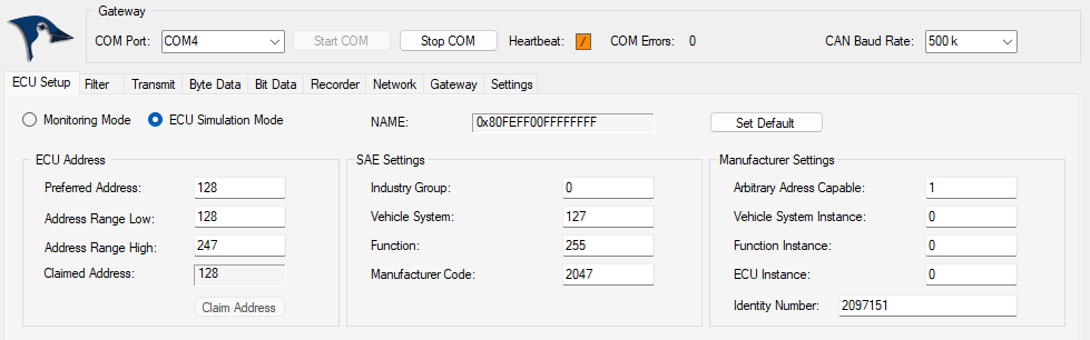
I set up one J1939-USB board to represent node 128 at 500k baud:
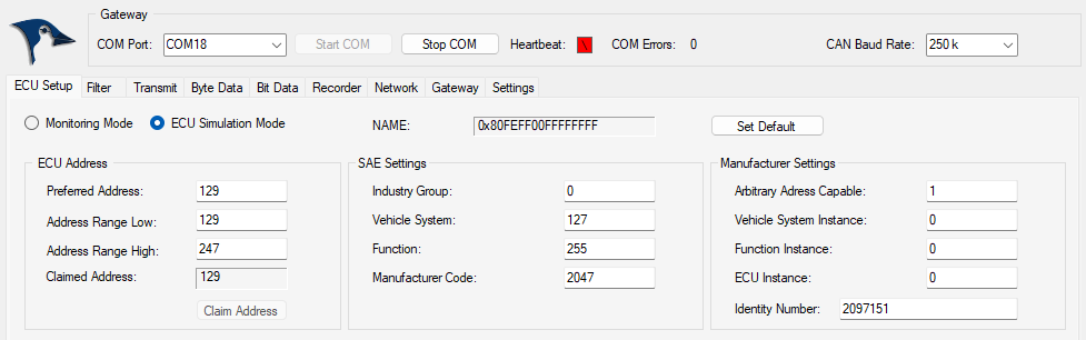
The second J1939-USB board was set up to represent node 129 at 250k baud:
The next image shows the data traffic at node 128:
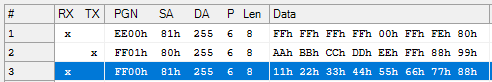
Row 1: Node 128 receives address claim from node 129.
Row 2: Node 128 transmits PGN FF01 hex.
Row 3: Node 128 receives PGN FF00 hex from node 129.
A similar scenario happened at node 129:
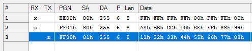
Row 1: Node 129 receives address claim from node 128.
Row 2: Node 129 receives PGN FF01 from node 128.
Row 3: Node 129 transmits PGN FF00.
After this first test, I assigned transmit frequencies to the PGNs, and the data traffic is demonstrated here:
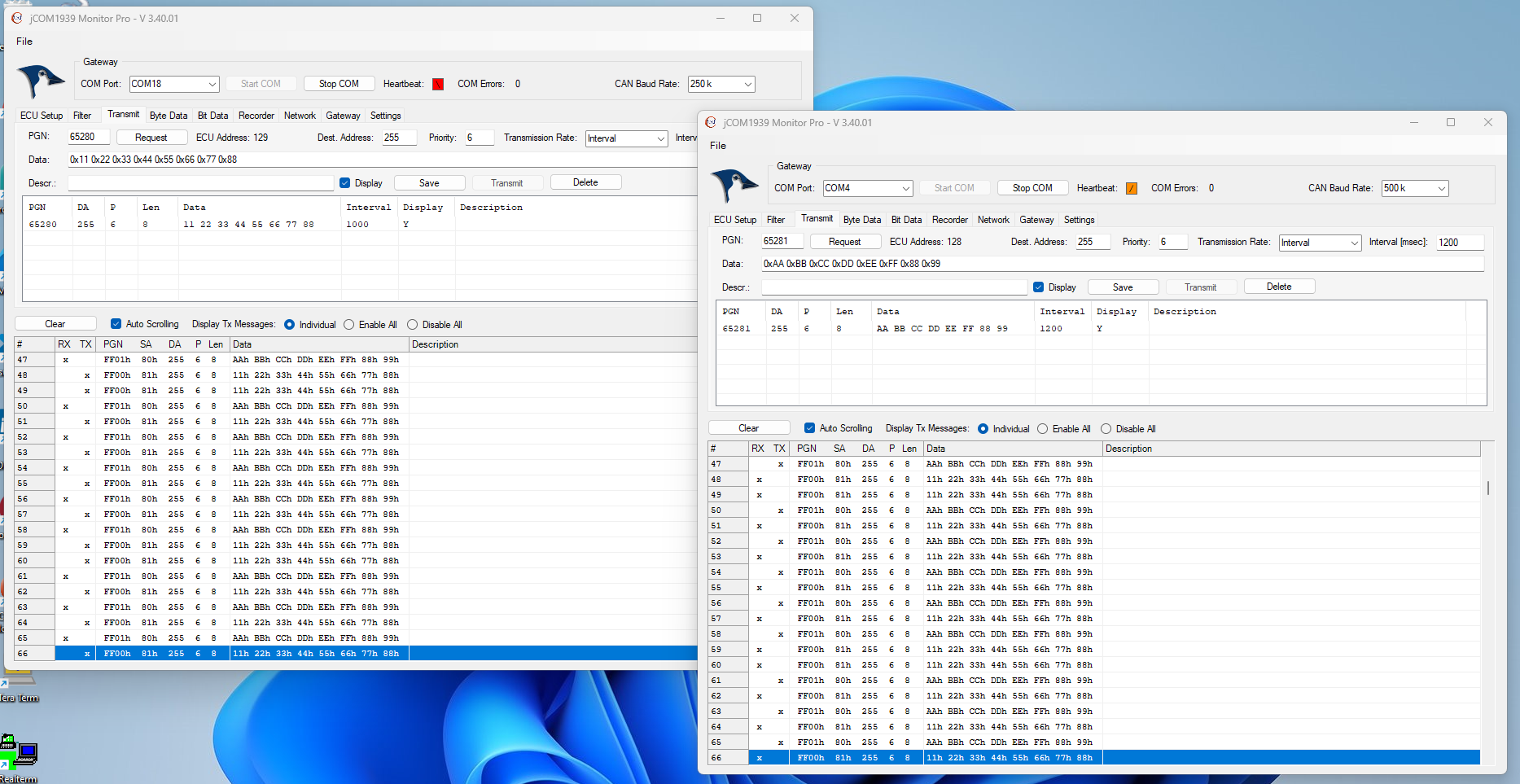
The above image shows two instances of the JCOM1939 monitor software, one assigned to node 128, the other to node 129.
The Arduino code is fairly simple, and I will only refer to the most important section:
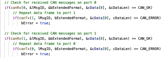
The code shows that CAN port 0 repeats every data frame it receives and transmits it per CAN port 1. The same happens the other way around.
The code can be easily extended to support message mapping, i.e., re-assigning message IDs (PGNs). The application can also be used as a CAN Repeater, Network Extender, and more.
Click here to download the Arduino code...

SAE J1939 Starter Kit And Network Simulator
Our J COM.J1939 Starter Kit And Network Simulator is designed to allow the experienced engineer as well as the beginner to experiment with SAE J1939 data communication without the need of connecting to a real-world J1939 network, i.e. a diesel engine. It may sound obvious, but in order to establish a network, you need at least two nodes, and that fact applies especially to CAN/J1939 where the CAN controller will basically shut down after transmitting data without receiving a response. For that reason, our jCOM.J1939 Starter Kit And Network Simulator consists of two J1939 nodes, namely our jCOM.J1939.USB, an SAE J1939 ECU Simulator Board With USB Port.
SAE J1939 250k/500k Baudrate Converter Using Arduino Due With Dual CAN Bus Port
In the past months, customers have approached me regarding a CAN Bus baud rate converter for SAE J1939 networks. The original SAE J1939 Standards Collection was limited to a baud rate of 250k to keep things simple and reliable. I don't know what triggered the decision to add the 500k baud rate. From a technical [...]
Local Interconnect Network (LIN) To Controller Area Network (CAN Bus) Converter
The LIN (Local Interconnect Network) bus is an inexpensive serial communications protocol, which effectively supports remote application within a car's network. It is particularly intended for mechatronic nodes in distributed automotive applications, but is equally suited to industrial applications. It is intended to complement the existing CAN network leading to hierarchical networks within cars.Controller Area Network [...]