 Loading... Please wait...
Recent Posts
SAE J1939 250k/500k Baudrate Converter Using Arduino Due With Dual CAN Bus Port
Posted by on

In the past months, customers have approached me regarding a CAN Bus baud rate converter for SAE J1939 networks. The original SAE J1939 Standards Collection was limited to a baud rate of 250k to keep things simple and reliable. I don't know what triggered the decision to add the 500k baud rate. From a technical standpoint, the SAE J1939 protocol can support any CAN Bus baud rate.
However, things tend to get more complex with the maximum baud rate of 1 MBit/sec, limiting the maximum physical network length and requiring extremely carefully installed wiring. Consequently, the limitation to 250k assured higher reliability and easier installation, which, in turn, lowered costs in various areas. I can only speculate that SAE gave in to multiple user requests for a higher baud rate given the vastly improved technology since the introduction of SAE J1939 and the demand for higher data throughput.
Be that as it may, the problem is that you can't mix baud rates within one network, and older J1939 units neither operate at a higher baud rate nor support automatic baud rate detection. As a result, these devices need a baud rate converter, and the market does not offer an acceptable solution.
The above image shows a setup with a baud rate converter, represented by the larger board to the right. The other two boards (i.e., our SAE J1939 simulator boards) represent two J1939 ECUs, one operating at 250k and the other at 500k CAN Bus baud rate. The baud rate conversion works in both directions, thus allowing full data exchange between the nodes.
Hardware
The baud rate converter hardware is based on the Arduino Due, and we offer two variants, which will both work using the same code:
- Arduino-based ECU Development Board With Dual CAN Bus Interface...
- Arduino-Due-Base ECU Development Board With Two CAN Bus Ports...
The above setup uses item 2.
Please be aware that both boards are not isolated.
Proof of Concept
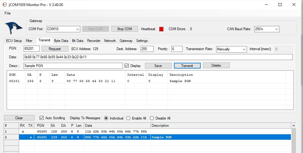
As mentioned previously, our setup included two simulated SAE J1939 nodes at address 128 and 129, respectively. One node operates at 250k, the other at 500k.
The next image shows our JCOM1939 Monitor software, in this case connected to the node running at 250k. In the lower part of the image you see the J1939 data, one received and one transmitted.
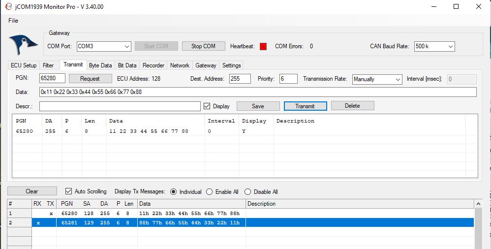
The following image shows the same, but for the 500k node:
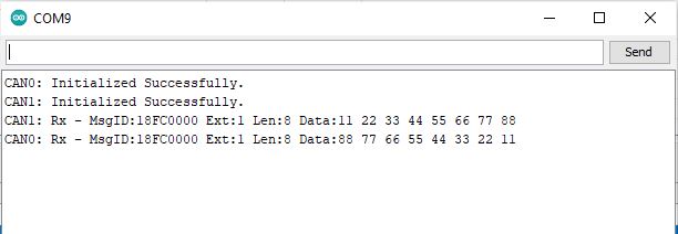
Last, but not least, a screen shot of the Arduino Serial Monitor window, showing both initialization results and data frame reception:
Download the code
I will not engage into a line-by-line explanation of the code. It is a simple code, and any experienced Arduino programmer will see what's going on. Otherwise, the code works "out of the box," meaning it can be easily loaded using the Arduino IDE.
Please be aware that we will not provide any technical support for the code since it is free. We will, however, gladly assist buyers of our hardware.

Exploring Arduino: Tools and Techniques for Engineering Wizardry
Exploring Arduino makes electrical engineering and embedded software accessible. Learn step by step everything you need to know about electrical engineering, programming, and human-computer interaction through a series of increasingly complex projects.
Arduino guru Jeremy Blum walks you through each build, providing code snippets and schematics that will remain useful for future projects. There are downloadable source code, tips and tricks, and video tutorials to help you master Arduino. In addition, you gain the skills you need to develop your microcontroller projects!