Recent Posts
OBD-II Data Logging With Raspberry Pi And PiCAN2 CAN Bus Interface
Posted by on

In all regularity, I receive inquiries from users attempting to connect their Raspberry Pi with PiCAN CAN Bus interface to their vehicle's OBD-II diagnostics port, and the questions asked prompted me to write down the essentials to consider for such a project.
Please, note: The following refers to reading CAN Bus data from a vehicle's OBD-II diagnostics port. Many users who contacted me, were under the impression that they can also transmit data into the CAN Bus network, which may result in unforeseeable, possibly negative - if not fatal - impact on the vehicle's performance.
Also, please aware that every vehicle brand and model has its distinct (proprietary) features, meaning they're not all the same. And yes, we are CAN Bus experts, but we are not vehicle specialists, and we cannot advise on data traffic on a 1972 BMW or a 2004 Toyota.
In other words, due to liability reasons, automobile manufacturers do not disclose information explaining their OBD-II data traffic.
Know Your OBD-II
The most important topic, though, is knowledge of OBD-II. It is well documented, and it's worthwhile taking the time to study it as the documentation will answer most of the questions you have (and even those you weren't aware of). Last, but not least, I must stress the point that OBD-II is a diagnostics technology, meaning it is not meant as a path to control vehicle functionality.
For more information, see:
The PiCAN2 CAN Bus HAT For Raspberry Pi
Let's address the hardware, i.e. the Raspberry Pi in combination with the PiCAN CAN interface.
The most important aspect is that you should use the SMPS variant of the PiCAN board.
SMPS stands for "Switch Mode Power Supply," and it allows you to power the entire Raspberry Pi system, including PiCAN HAT (and possibly a display) from your vehicle's 12 VDC battery power.
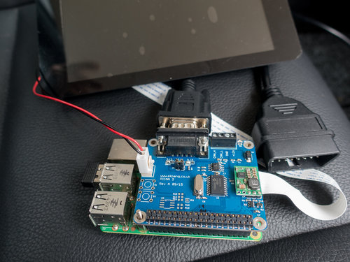
The SMPS option is represented by the little green piggy-back board on top of the PiCAN2-SMPS interface board as shown in the image above.
To connect the system to the OBD-II diagnostics board, you will need a cable, and there are two choices:
1. Connecting to the PiCAN's DB9 connector

In this case, you will need an OBD-II to DB9 cable, which is immediately compatible with this setup.
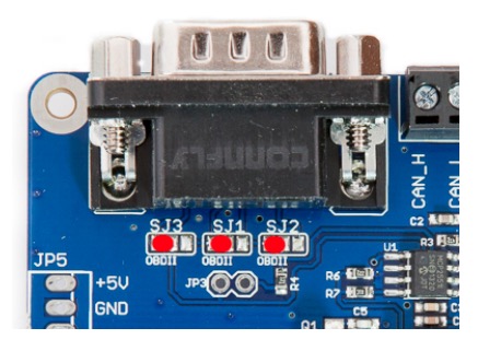
However, please assure that you solder the onboard jumpers to support OBD-II as shown in the image.
For further information, please see the board's user manual.
2. Connecting to the PiCAN's terminal

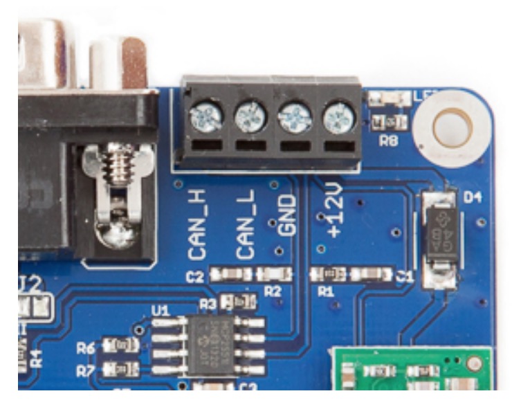
In this case, you will need an OBD-II open-ended cable, which requires some careful attention to the wiring.
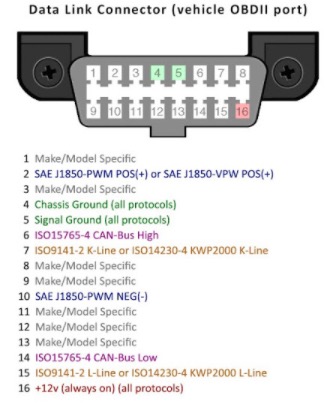
Please pay attention to the OBD-II connector's pinout and wire coloring and how to connect the signals (CAN_H, CAN_L, power supply) to the terminal.
For further information, please refer to the cable description and the user manual.
3. Termination Resistor
When you connect the PiCAN2 board to a vehicle, you most likely won't need to activate the termination resistor. It can be assumed that the vehicle network is already properly terminated.
4. The OBD-II Diagnostics Connector
Make sure, you connect CAN-H on the board to CAN_H on the diagnostics connector, and do the same with CAN_L.

PiCAN2 Software Setup
In regards to the software, many users start with the standard PiCAN tools such as candump (again, see the user manual), however, without understanding which CAN Bus baud rate they should use (in most cases, it's 500k, but that is not guaranteed for each vehicle), and it is mandatory that you match the baud rate between the board and your vehicle.
Also, in case your setup still doesn't work, please assure that you know your OBD-II, because the diagnostics port provides several options and they may change depending on the vehicle's brand, type, and age. For more information, see https://en.wikipedia.org/wiki/On-board_diagnostic...
Another point where users get confused, especially when reading the CAN data doesn't work, are the correct setting in the /boot/config.txt file. To make it a point, there is only one version that works (despite some misleading online forum entries I've seen):
dtparam=spi=on
dtoverlay=mcp2515-can0,oscillator=16000000,interrupt=25
dtoverlay=spi-bcm2835-overlay
For more information on troubleshooting your PiCAN setup, see also the following posts:
- Troubleshooting your PiCAN2 CAN Interface Board for Raspberry PI
- PiCAN2 CAN Bus Board for Raspberry Pi - Functionality Test
For more information on OBD-II data logging with the PiCAN CAN Bus interface board, see also:
If you prefer to circumvent any potential issues, I recommend going with our Raspberry Pi System With Single CAN Bus Interface and choosing the SMPS option. The system comes with a pre-installed Raspbian operating system, and all systems undergo a functionality test before shipping.
OBD-II Literature
- Automotive Diagnostic Systems: Understanding Obd-I & Obd-II...
- OBD-2 Automotive Code Encyclopedia and Cross-Reference Guide: Includes Volume/Voltage/Current/Pressure Reference and OBD-2 Codes...
- How To Use Automotive Diagnostic Scanners: - Understand OBD-I and OBD-II Systems - Troubleshoot Diagnostic Error Codes for All Vehicles...
- OBD-II & ELECTRONIC ENGINE MANAGEMENT SYSTEMS TECHBOOK...
- OBDII Diagnostics Made Easy...
 Loading... Please wait...
