Blog
Recent Posts
Why the PiCAN-M with SMPS Cannot Power Raspberry Pi 5 — and the Simple Workaround
Posted by on
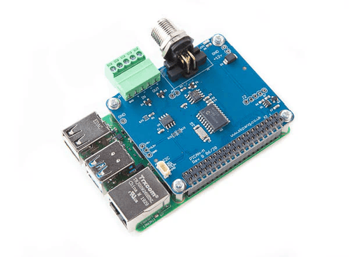
 The PiCAN-M HAT from Copperhill Technologies is a specialized interface developed exclusively for marine applications and specifically targets NMEA 2000 networks. NMEA 2000 is the standard backbone for modern marine electronics, used to interconnect engines, chart plotters, sensors, and onboard monitoring systems. In its standard version without SMPS, the PiCAN-M HAT is powered directly from the Raspberry Pi and is intended for installations where the Raspberry Pi already receives stable power from the vessel’s electrical system. This configuration emphasizes reliable NMEA 2000 communication and electrical robustness, making it well suited for marine development, diagnostics, and fixed installations with controlled power distribution.
The PiCAN-M HAT variant with integrated SMPS is designed for marine environments where a higher-voltage onboard supply, typically 12 V or 24 V, is readily available. The onboard switched-mode power supply converts this voltage to a regulated 5 V rail for the Raspberry Pi, reducing wiring complexity and eliminating the need for an external DC-DC converter. This approach is particularly useful in compact marine enclosures and retrofit projects. As marine electronics and Raspberry Pi models evolve, overall system power requirements should be evaluated carefully to ensure stable operation, especially when higher-performance Raspberry Pi boards are used alongside NMEA 2000 networks.
However, a limitation arises when using the SMPS version of the PiCAN-M HAT with a Raspberry Pi 5. The onboard SMPS (switched-mode power supply) is rated for a maximum output current of 3 A, whereas the Raspberry Pi 5 is designed to draw up to 5 A under load. As a result, powering a Raspberry Pi 5 directly from the PiCAN-M SMPS can lead to undervoltage conditions and unstable operation. To address this, we have developed a reliable workaround that uses an external DC/DC converter to meet the higher current demands while still retaining full NMEA 2000 functionality.
For more information, see also our post Testing PICAN CAN Bus HATs with the Raspberry Pi 5...
Please note that the workaround described below is a conceptual solution at this stage. It is being shared in response to customer requests and has not yet undergone full validation or extended testing. Additional verification and refinements will follow. Until then, implementing this approach is done at your own risk.
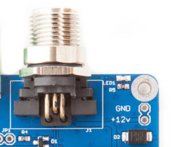
The PiCAN-M board—whether equipped with SMPS or not—includes a dedicated power section that allows you to access or supply 12 VDC, as illustrated here:

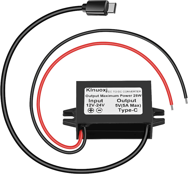
This connection point can be used to feed the 12–24 VDC input of an external DC/DC converter, as shown in the following image.
The selected converter provides a regulated 5 V output via a USB-C connector, which plugs directly into the Raspberry Pi 5 and supplies the required current independently of the PiCAN-M’s onboard power circuitry.
This approach allows the PiCAN-M to remain focused on NMEA 2000 communication while the Raspberry Pi 5 is powered by a converter sized appropriately for its higher current demands. For ordering information and detailed technical specifications of the recommended DC/DC converter, please refer to DC 12V/24V to 5V USB C Step Down Converter.
Adafruit HUZZAH32 ESP32 Feather Board – WiFi, Bluetooth & Battery Power for IoT Projects
The Adafruit HUZZAH32 Feather Board brings Espressif’s powerful ESP32-WROOM32 module into Adafruit’s popular Feather ecosystem. It offers built-in WiFi and Bluetooth connectivity, dual-core performance, and efficient battery management — making it an excellent choice for Internet of Things (IoT) and embedded applications that demand portability, wireless communication, and reliability. Compact Power for Wireless Projects The HUZZAH32 is [...]
Raspberry Pi PICAN2 Functionality Test With Two PICAN2 HATs
The following is yet another post on testing the PICAN2 - CAN Bus Interface for the Raspberry Pi, however, with a different approach. In this case, we utilize two identical PICAN2 boards and connect them per the CAN Bus (CAN_H to CAN_H, CAN_L to CAN_L) as shown in the image above.In the past, we have [...]
SAE J1939 Programmable Data Traffic Simulator For Generating Diesel Engine Signals (PGNs)
The following represents an update on our current development activities, in this case the jCOM.J1939 Programmable Data Traffic Simulator (a first prototype is shown in the image to the left).In short, the plan is that the device is being set up by means of a Windows software and then runs the programmed PGNs (Parameter Group [...]
CAN FD To USB Gateway Project With Teensy 3.2 And Microchip MCP2517FD CAN FD Controller
Our Teensy 3.2 With CAN FD Breakout Board provides all the components needed to create your CAN FD to USB-Micro Gateway. The board comes with the Microchip MCP2517FD CAN FD controller, while the Teensy 3.2 provides the USB connection. It also has an onboard 5 VDC regulator and reverse-voltage protection. The MCP2517FD is a cost-effective and small-footprint CAN [...]
SAE J1939 Monitor, Analyzer, And ECU Simulator For Windows - New Byte & Bit Editing Mode
The jCOM1939 Monitor Software by Copperhill Technologies is the ideal software tool for monitoring, analyzing, and simulating SAE J1939 data traffic. The program links to our jCOM.J1939.USB ECU Simulator Board that operates as an SAE J1939 to USB (or UART) gateway. This comprehensive and easy-to-use, easy-to-understand Windows software illustrates not only SAE J1939 data traffic; it also allows the [...]
Controller Area Network (CAN Bus) - Physical Layer And Bus Topology
The following is an excerpt from A Comprehensible Controller Area Network by Wilfried Voss. The ISO/OSI Reference Model specifies seven levels starting with the physical connection up to the actual user application, i.e., the Application Layer. The standard CAN Bus implementation neglects the connection between the Data Link Layer and the Application Layer to save on relevant memory resources [...]
CAN Bus Over Ethernet Interface For Internet-of-Things (IoT) Applications
The EtherCAN HS by Kvaser is a real-time Ethernet-to-CAN gateway interface that, when connected over the Internet to an Ethernet-equipped PC, enables remote CAN Bus data access from anywhere in the world. The built-in Power-over-Ethernet eradicates the requirement for a separate power cable when it is not possible to power the device from the CAN Bus network. Kvaser's EtherCAN [...]
Galvanically Isolated CAN Bus Transceivers Protect Networks Against Destructive Energy
High noise levels on a CAN bus network have the potential to destroy CAN bus transceivers. This noise originates mainly from two sources, ground loops and electrical line surges.Protecting a network against this destructive energy requires the galvanic isolation of the CAN bus system from other local node circuitry. For more information on Controller Area [...]
OBD-II Data Logging With Raspberry Pi And PiCAN2 CAN Bus Interface
In all regularity, I receive inquiries from users attempting to connect their Raspberry Pi with PiCAN CAN Bus interface to their vehicle's OBD-II diagnostics port, and the questions asked prompted me to write down the essentials to consider for such a project.Please, note: The following refers to reading CAN Bus data from a vehicle's OBD-II [...]
 Loading... Please wait...

