 Loading... Please wait...
Recent Posts
The PiCAN Advantage: High-Performance CAN Interfaces for Raspberry Pi
Posted by on
 The PiCAN series is a comprehensive line of CAN Bus interface boards (HATs) developed specifically for the Raspberry Pi platform. Designed and manufactured by Copperhill Technologies, these boards offer robust support for both Classical CAN (2.0A/B) and the more advanced CAN FD protocols. The product line is engineered to meet the diverse needs of automotive, industrial, and marine applications, ranging from simple single-channel CAN interfaces to dual-channel, isolated, and feature-rich variants with onboard power supplies, real-time clocks, GPS modules, and even Ethernet or LIN connectivity.
Each PiCAN board adheres to the HAT standard for Raspberry Pi compatibility, supporting models from the compact Pi Zero to the more powerful Pi 4 and Pi 5. Most boards integrate seamlessly with Linux systems via SocketCAN, enabling developers to interact with the CAN network through familiar tools and programming interfaces. Options for onboard DC/DC converters allow the Raspberry Pi to be powered directly from 12V or 24V vehicle or industrial power sources, making deployment in embedded environments straightforward and reliable.
The PiCAN family addresses a wide range of use cases, including CAN data logging, diagnostics, protocol bridging, industrial automation, and marine navigation. With support for standards such as SAE J1939, NMEA 2000, LIN, and SENT, PiCAN boards provide a powerful and flexible foundation for building CAN-based applications using the Raspberry Pi.
PiCAN3 CAN Bus HAT for Raspberry Pi with 3A SMPS & RTC
 The PiCAN3 board equips a Raspberry Pi 4 with a high-performance CAN 2.0B interface using Microchip’s MCP2515 CAN controller and MCP2551 transceiver, supporting standard/extended frames at speeds up to 1 Mbps. It offers both a 9-pin D-Sub (DB9) connector and a 3-way screw terminal for CAN bus wiring, with a built-in 120 Ω terminator and a solder-bridge for OBD-II/J1939 DB9 pin configurations. A key feature is the onboard 3 A switch-mode power supply (SMPS) accepting 6–20 V input, which can power the HAT, the Raspberry Pi itself, and peripherals – ideal for vehicular and industrial voltage sources (with reverse-polarity protection). The PiCAN3 also includes a PCF8523 real-time clock (RTC) for timestamping and time-keeping (battery backup supported). It follows the HAT mechanical standard (mounting holes) and uses GPIO25 as an interrupt for CAN traffic. Status LEDs and footprints for optional add-ons (LCD or buttons) are provided to aid development. Software integration is straightforward via SocketCAN – once the SPI interface is enabled and the driver installed, the CAN bus appears as
 can0 in Linux, accessible to C/Python code and utilities. Use cases: With its robust design and wide 6–20 V power input, PiCAN3 is suited for automotive CAN projects, diagnostics, industrial control, and robotics, especially where an accurate RTC and single-supply power convenience are required. More information...
PiCAN2 CAN Bus Interface for Raspberry Pi
 The PiCAN2 is a second-generation CAN HAT providing classical CAN 2.0A/B support up to 1 Mbps via the same MCP2515/MCP2551 chipset. It attaches via the 40-pin header and complies with the Pi HAT form factor. PiCAN2 features a DB9 and screw terminal for CAN wiring, compatible with OBD-II and SAE J1939 networks (the DB9 can be set to the OBD-II pinout). An on-board 120 Ω termination resistor and interrupt (GPIO25) facilitate reliable bus communication. The HAT is powered directly from the Pi’s 5 V rail (no onboard regulator in the base model), and it fully supports Raspberry Pi 4 and even Pi 5 SBCs. Like other PiCAN devices, it uses SocketCAN – once installed, it appears as
 can0 for use with can-utils or custom software. This board is a cost-effective solution for adding one CAN channel to any Raspberry Pi and has been widely used for CAN logging, vehicle OBD telemetry, and prototyping of CAN-based systems.
PiCAN2 SMPS Variant: An enhanced PiCAN2 version integrates a 5 V/1 A SMPS for external power input (6–20 V) via the DB9 or terminal block. This allows the Raspberry Pi and HAT to be powered from automotive power (e.g. a 12 V battery) through the HAT. It includes reverse polarity protection and high-efficiency conversion. However, due to the 1 A limit, this variant is not recommended for power-hungry boards like Raspberry Pi 4/5, which typically require ~3 A. It is best used with Pi 2 or Pi 3 or in cases where the Pi’s own consumption is modest. All other features (CAN transceiver, connectors, termination, etc.) match the standard PiCAN2. The SMPS-equipped PiCAN2 offers greater flexibility in field deployments by simplifying power wiring – one can power the whole Pi from a vehicle’s 12 V system – but designers must mind the current budget. More information...
PiCAN2 Duo (Dual CAN Channels) for Raspberry Pi
 The PiCAN2 Duo provides two independent CAN 2.0B channels on one HAT, useful for applications like CAN bridging or logging two buses simultaneously. It implements two MCP2515 controllers and dual MCP2551 transceivers, each channel running up to 1 Mb/s and accessible via a 4-way screw terminal (each CAN pair has CANH, CANL, and shared ground/reference). The board has a 120 Ω terminator on each channel (jumper/solder bridges to enable or disable as needed) and uses GPIO25 and GPIO24 for interrupts (one per CAN controller). Notably, the PiCAN2 Duo for Raspberry Pi 4 model includes a 5 V, 3 A SMPS power supply on-board, accepting 7–24 V input, which can power both the HAT and a Pi 4 reliably. This high-current DC/DC converter lets you run a Pi 4 in automotive environments from a single 12 V supply, with built-in polarity protection. The board has status LEDs for each CAN channel and provisions for attaching an LCD or other add-ons. Once the SocketCAN driver is installed and SPI enabled, the two CAN ports appear as
 can0 and can1 in Linux, allowing simultaneous CAN operations on both channels. Use cases: The PiCAN2 Duo is ideal for scenarios requiring dual-CAN, such as vehicle network gateways (e.g. bridging CAN FD to CAN 2.0, or isolating engine and chassis CAN segments), or logging interactions between two CAN buses in real time. The robust 3 A SMPS makes it a good fit for Pi 4-based automotive controllers where the HAT and Pi can be fed from the vehicle power bus.
Note: An earlier PiCAN2 Duo model (for Pi 2/3) without the 3 A regulator exists, as well as an isolated variant. The PiCAN2 Duo for Pi 2/3 uses the same dual MCP2515 design and provides dual CAN channels via screw terminals, but it must be powered from the Pi’s 5 V (or an external regulator) and is typically used on older Raspberry Pi boards. More information...
PiCAN-M NMEA 0183 & 2000 HAT (Marine CAN Bus)
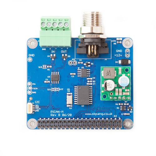 The PiCAN-M is a special HAT designed for marine data networks, combining a CAN Bus interface for NMEA 2000 (the marine standard based on CAN at 250 kbps) and a serial interface for NMEA 0183 (RS-422). It features a Micro-C connector to join the marine NMEA 2000 bus (CAN physical layer) and a 5-pin terminal block for NMEA 0183 signals. The CAN controller (for N2K) uses the same MCP2515 chipset (supporting Classical CAN frames), and the NMEA 0183 port uses a built-in RS422 transceiver tied to the Pi’s UART (appearing as a TTY serial port). This allows a Raspberry Pi to act as a marine gateway, translating between NMEA 2000 and NMEA 0183 or logging data from both. The board has an LED indicator (on GPIO22) for status, and also includes a Qwiic (I²C) connector for integrating sensors (useful for adding compass, environmental sensors, etc., commonly used with marine systems). Out of the box, the PiCAN-M is compatible with popular open-source marine software like OpenCPN, OpenPlotter, Signal K, and CANBoat, which can interpret and display navigation data. Power: The base PiCAN-M does not include an onboard SMPS, so it cannot be powered from the N2K bus directly (NMEA 2000 networks usually supply devices with 12 V). It must be powered via the Pi’s 5 V (or one can use the upgraded SMPS version). Copperhill explicitly notes the base model cannot take power from the NMEA 2000 connection.
PiCAN-M with SMPS: This variant adds a 3 A SMPS (12 V input) to allow powering the Raspberry Pi + HAT from the boat’s power/N2K backbone. With 7–24 V DC input range, it’s tailored for 12 V or 24 V systems, providing sufficient current for a Pi 4 under load. The SMPS version is otherwise identical in function: Micro-C for CAN, RS422 terminal for 0183, and it significantly simplifies installation by letting the Pi draw from vessel power without a separate regulator. The PiCAN-M has an available optional metal enclosure for Pi 4, making it a neat marine-grade unit. Use cases: Build a Raspberry Pi navigation computer or IoT gateway on a boat – PiCAN-M can feed GPS, AIS, depth sounder, wind, engine data (via NMEA 2000) to the Pi for logging or display, while also bridging older NMEA 0183 instruments. For hobbyist sailors and marine tinkerers, it provides a compact solution to interface modern CAN-based marine networks and legacy serial devices simultaneously. More information...
PiCAN FD Series (CAN FD Support) – Overview
Copperhill’s PiCAN FD line introduces support for CAN FD (ISO 11898-1:2015), which allows data-phase bit rates up to 8 Mbps and up to 64-byte payloads. All PiCAN FD boards use Microchip’s MCP2517FD or MCP2518FD CAN FD controllers (connected via SPI) along with MCP2562FD transceivers for the physical layer. These controllers are backward-compatible with Classical CAN 2.0A/B, so a single interface can handle standard CAN and CAN FD frames in mixed networks. SocketCAN support is provided (the devices appear as canX and support CAN FD frame types), so Linux tools and libraries can be used to send/receive CAN FD. The PiCAN FD family spans multiple variants with additional features: some have extra communication ports (LIN, Ethernet), some have dual channels, some offer isolation, and others include power supplies or GNSS receivers. Below are individual summaries for each model.
PiCAN FD “Standard” Board with Real-Time Clock (Single Channel)
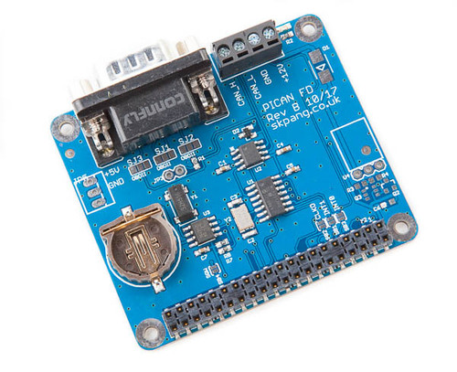 This is a single-channel CAN FD HAT similar in layout to PiCAN2, but upgraded for FD and with an onboard RTC. It uses the MCP2517FD controller and MCP2562FD transceiver, enabling Classical CAN and CAN FD up to 8 Mbps. A PCF8523 RTC is included for timestamping and timekeeping (battery slot provided). The board provides a 9-pin DB9 connector and screw terminal for CAN, with jumpers to select termination (120 Ω on/off) and to configure the DB9 for OBD-II pinout. Notably, it features an optional onboard power supply: a 5 V, 1 A SMPS which can feed the Raspberry Pi via the HAT (through the DB9 or terminal input). The “with SMPS” SKU comes with this regulator populated, supporting about 6–20 V DC input to power the Pi. This lets a user power the whole setup from a vehicle battery or industrial 12 V rail easily. When installed, the PiCAN FD board’s power input (on the DB9 or terminal VIN pin) can drive the Pi – in the same manner as PiCAN3 – simplifying power wiring. If not using the SMPS, the Pi is powered normally via USB or GPIO 5 V and the HAT draws from the Pi. Aside from CAN FD capability, the rest of the design mirrors earlier PiCANs: four mounting holes, LED indicators, interrupt on GPIO25, etc. Like others, it integrates with Linux SocketCAN (appearing as
 can0) for use with tools in C or Python. Applications: This board is a go-to for adding a single CAN FD channel to a Raspberry Pi for modern automotive networks or any CAN FD-enabled machinery. The addition of an RTC makes it attractive for data logging applications, where timestamping CAN data (even during power-offs) is needed. More information...
PiCAN FD with LIN Bus (CAN FD + LIN Controller)
 This HAT combines a CAN FD channel with a LIN bus interface for applications requiring both protocols (common in automotive sensor networks). The CAN FD functionality is handled by the MCP2518FD controller (with up to 8 Mbps data rate), and a separate Microchip dsPIC33 microcontroller acts as a LIN co-processor. The LIN interface supports SAE J2602 / LIN 2.x style networks and can be configured either as LIN master or slave via a jumper. Communication between the dsPIC33 and the Pi is done through UART (ttyS0), using simple ASCII command protocols to send/receive LIN frames. Copperhill provides a Python3/Tkinter GUI example for LIN to demonstrate sending and receiving LIN messages through this HAT. In practice, the PiCAN FD LIN board allows a Raspberry Pi to participate in LIN networks (e.g. automotive comfort electronics) while also interfacing with the higher-speed CAN/CAN FD bus. It has status LEDs for LIN activity and uses the standard 4-way screw terminal for the LIN bus wiring. The board can be purchased with or without a 3 A SMPS regulator. The SMPS version accepts 7–24 V to power both the Pi and the HAT (just like other SMPS variants). This is particularly useful in automotive use-cases where a single 12 V input can run the whole system. Use cases: bridging data between a car’s LIN sub-bus (e.g. window controllers, sensors) and the main CAN bus, or testing LIN devices with a Raspberry Pi. With this HAT, a developer can monitor and control LIN devices through the Pi (issuing LIN frames via simple serial commands) while simultaneously handling CAN FD traffic – useful in automotive test benches and reverse-engineering projects. More information...
PiCAN FD with SAE J2716 SENT Interface
 This model adds support for the SENT protocol (Single Edge Nibble Transmission) alongside a CAN FD channel. SENT is a one-way serial sensor communication standard (commonly used for automotive sensors like pressure, temperature, etc.). The HAT includes a dsPIC33 microcontroller to handle two SENT channels (each configurable as SENT transmitter or receiver). These channels use dedicated screw terminal pins and can output 5 V to power external sensors if needed. Like the LIN variant, the SENT microcontroller communicates with the Pi via UART with ASCII commands. This allows the Pi to read sensor data from SENT devices or generate SENT signals. The CAN FD part uses MCP2518FD and functions as usual. The board targets automotive developers who need to interface a Pi with SENT-based sensors while also connecting to the vehicle’s CAN/CAN FD network. Copperhill’s documentation notes that example Python software is provided for SENT decoding. The HAT can be ordered with an optional 3 A SMPS module to run from 7–24 V vehicle power. With the SMPS installed, it becomes a single-supply solution for reading both CAN FD and SENT sensor data using a Raspberry Pi. Example: using this board, one could build a Raspberry Pi-based data acquisition system that reads a high-resolution SENT turbocharger speed sensor and sends the data onto the CAN FD bus (or logs it). Having two SENT channels means it can handle, for instance, two wheel speed sensors or any pair of SENT devices simultaneously. More information...
PiCAN FD with GPS/GNSS (u-blox NEO-M8M)
 This variant integrates a u-blox NEO-M8M GNSS receiver module on the HAT, in addition to a CAN FD interface. The NEO-M8M is a multi-constellation receiver capable of tracking GPS, Galileo, GLONASS, and BeiDou satellites concurrently for improved accuracy. The module supports up to 72 channels and outputs position/time data. It connects to the Pi either via USB (the board provides a USB-C port) or via UART/I²C – meaning you can either use it as a USB GPS device or directly interface it as a serial GPS. There’s an SMA connector on the HAT for an external GPS antenna, which is typically required for good reception. With this HAT, a Raspberry Pi can receive precise GPS time and location, which is extremely useful for timestamping CAN data or creating a moving datalogger. The MCP2518FD on board provides the CAN FD channel (classic CAN 2.0 and FD up to 8 Mbps) so the Pi can both log CAN traffic and geo-tag it with GPS coordinates in real time. The HAT has a fix status LED for the GNSS as well. Software-wise, the GPS can be used with standard GPS daemons (e.g. gpsd) or u-blox’s u-center software (when connected via USB). As with others, an SMPS version is available: it includes a 3 A regulator (7–24 V input) so that a single external supply can power the Pi + HAT. This is convenient for vehicle data logging – the HAT can be fed from the car’s battery and will power the Pi, while providing both CAN data and GPS data to the Pi. Applications: Vehicle fleet tracking and CAN logging, where each CAN message log is timestamped with real time and GPS position; building a standalone telematics unit on a Pi; or any IoT project that requires both CAN bus interfacing and location data (farm equipment, marine vehicles, etc.). With multi-GNSS and assisted GPS capabilities, the NEO-M8M offers robust positioning even in challenging signal conditions. More information...
PiCAN FD HAT with 10Base-T1L (Single-Pair Ethernet, Long Reach)
 This unique HAT combines CAN FD with an Ethernet interface designed for industrial environments. It features an Analog Devices ADIN1110 MAC/PHY providing a 10Base-T1L port (10 Mb/s single-pair Ethernet, long-reach) and an MCP2518FD for CAN FD. The 10Base-T1L standard (IEEE 802.3cg) allows Ethernet communication over a single twisted pair up to 1700 m of cable, making it useful in factory automation or building infrastructure where long cable runs occur. The ADIN1110 chip on the HAT implements both the PHY and a MAC with SPI interface to the Pi, effectively giving the Pi an Ethernet interface accessible via SPI. This port is exposed on a 4-pin terminal (SPE connector) since single-pair Ethernet typically uses either terminal blocks or specific connectors (instead of RJ45). With this HAT, a Raspberry Pi can bridge data between a CAN FD network and an Ethernet (10Base-T1L) network, or simply be concurrently connected to both. For example, it could connect a CAN FD sensor network to an Ethernet-based controller network. The CAN FD supports up to 8 Mbps in the data phase and is backward compatible with CAN 2.0, while the Ethernet side supports autonegotiation and includes diagnostic features like cable diagnostics and link quality monitoring. Power and design: The board does not include an SMPS (it uses Pi’s 5 V supply), so if long-distance power is needed, one might use PoE on T1L via external injectors or simply power the Pi normally. This HAT is clearly targeted at industrial IoT scenarios: 10Base-T1L is suited for process automation (able to reuse existing single-pair cabling in plants). Having CAN FD and T1L together means the Pi can act as a protocol converter or gateway between legacy CAN devices and modern Ethernet systems. The presence of an I²C (Qwiic) connector also allows additional sensor integration if needed. This combination is relatively specialized – users working with building automation (e.g. BACnet over single-pair) or new automotive Ethernet (IEEE 802.3cg is also being evaluated for in-vehicle networks) could experiment with this board. More information...
PiCAN FD HAT with 10Base-T1S (Single-Pair Ethernet, Multi-drop)
 The 10Base-T1S HAT is similar to the T1L version but uses Microchip’s LAN8651 MAC-PHY for 10Base-T1S Ethernet. 10Base-T1S (802.3cg short-reach) is a multi-drop Ethernet suitable for up to 25 m networks with multiple nodes on the same cable (using a bus topology rather than point-to-point). It’s being adopted in automotive for connecting multiple ECUs on one lightweight harness segment (also known as 10BASE-T1S Ethernet “clusters”). The HAT’s LAN8651 supports features like PLCA (Physical Layer Collision Avoidance) to coordinate channel access among up to 8 nodes on the line, allowing deterministic, collision-free communication on the shared medium. For the Raspberry Pi, this means the HAT provides an Ethernet interface (via SPI to the LAN8651) that can join or form a multidrop single-pair Ethernet network, plus a CAN FD controller (MCP2518FD) for the CAN side. The CAN FD capabilities mirror those of other boards (1 Mbps arbitration, 8 Mbps data phase). This HAT, therefore, enables bridging between CAN FD and a 10Base-T1S segment – something that might appear in future automotive architectures (for instance, connecting CAN FD sensors to an Ethernet backbone). Additionally, it can just be used to give the Pi a novel network interface for experiments with T1S (which can support both star and bus topologies for up to 8 MACs). The hardware includes an I²C connector as well, presumably for sensor expandability. Note: Both T1L and T1S HATs are relatively advanced and likely require specific driver support (Copperhill provides drivers/utilities on GitHub for the T1L/T1S chips). They cater to developers working on the cutting edge of combining CAN FD and Ethernet on small form-factor computers, bridging two important industrial/automotive network types. More information...
PiCAN FD Duo (Dual-Channel CAN FD) with Real-Time Clock
 This is a dual-channel CAN FD HAT (two independent CAN FD ports) analogous to the PiCAN2 Duo but upgraded to CAN FD and with an RTC. The PiCAN FD Duo uses dual MCP2517FD controllers and two MCP2562FD transceivers, giving two CAN FD channels accessible via a single 4-way terminal block (likely two pairs for CAN1 and CAN2). Each channel supports Classical CAN and CAN FD (up to 8 Mbps data rate) and has its own interrupt line to the Pi’s GPIO (the designers used different GPIOs, e.g. 25 and 5, to separate interrupts). A PCF8523 RTC is onboard (battery-backed) for timestamping, similar to the single-channel FD board. The board includes termination options for both CAN lines (probably jumpers to connect 120 Ω on each) and status LEDs per channel. Copperhill offers the FD Duo in two versions: one with just the RTC, and another that also includes a 3 A SMPS to power the Pi. The SMPS-equipped version takes 7–24 V in, enabling one supply operation even with power-hungry Raspberry Pi 4 boards. With the SMPS, it can easily be used in vehicles or industrial sites by powering the Pi via the HAT. Functionally, the dual CAN FD appears in software as
 can0 and can1. This is ideal for working with multiple CAN buses or logging two CAN FD networks concurrently. For example, a PiCAN FD Duo could monitor an automotive HS-CAN (500 kbps) on one channel and a CAN FD powertrain bus (2 Mbps/5 Mbps FD) on the other, all time-stamped by the RTC. Applications: automotive gateways (passing or filtering messages between two CAN/CAN FD networks), or complex test setups where a Pi needs to simulate or log two CAN buses. The presence of the RTC ensures accurate timing for data analysis. Moreover, with CAN FD’s extended data length, one could even imagine bridging two buses at different speeds by reading from one and writing aggregated data to another. The PiCAN FD Duo’s robust power option (in SMPS variant) and dual capability make it a very powerful HAT for modern CAN development and prototyping. More information...
PiCAN FD Zero (for Raspberry Pi Zero)
 The PiCAN FD Zero brings one CAN FD channel to the compact Raspberry Pi Zero form factor. It is essentially a smaller HAT/pHAT that uses the MCP2518FD controller and MCP2562FD transceiver, identical in capability to the full-size PiCAN FD, but tailored to the Pi Zero’s size and GPIO layout. The CAN connection is via a 4-pin screw terminal (CANH, CANL, GND and an optional VIN) rather than a DB9 to keep the footprint small. Despite its size, it still includes a 120 Ω terminator (likely fixed or jumper-able) and an indicator LED. A key design element is that it can be obtained with a built-in 1 A SMPS as well. The SMPS version of PiCAN FD Zero allows a 6–20 V input (on the VIN terminal) to power both the Pi Zero and the HAT. This is very useful for embedding a Pi Zero in vehicles or machines, as it simplifies power wiring (the Pi Zero’s lower current needs fit within 1 A easily). The PiCAN FD Zero also includes a Qwiic/QT connector for I²C sensors, acknowledging that Pi Zero is often used in space-constrained sensor logger projects. In terms of performance, it provides the full CAN FD feature set (up to 8 Mbps data rate) and appears as
 can0 in Linux via SocketCAN. It uses GPIO25 as interrupt as well. Target use: Owing to the Pi Zero’s small size, this HAT enables extremely compact CAN FD nodes or loggers – for instance, a Pi Zero W with PiCAN FD Zero could be a wireless CAN FD sniffer or part of a distributed sensor network in an automobile. It’s also cost-effective for building multiple CAN FD nodes (the Pi Zero 2 W’s quad-core CPU can handle CAN at high rates while logging or processing). Overall, PiCAN FD Zero brings the modern CAN capabilities to the smallest Pi, making CAN FD accessible in projects where size, weight, and power are at a premium. (Note: Copperhill also mentioned a similar CANPico for the Raspberry Pi Pico microcontroller, which is a separate product – the PiCAN FD Zero is specifically for Pi Zero SBCs.) More information...