Blog
Recent Posts
JCOM1939 Monitor Software - A Critical SAE J1939 Diagnostic and Analysis Tool
Posted by on
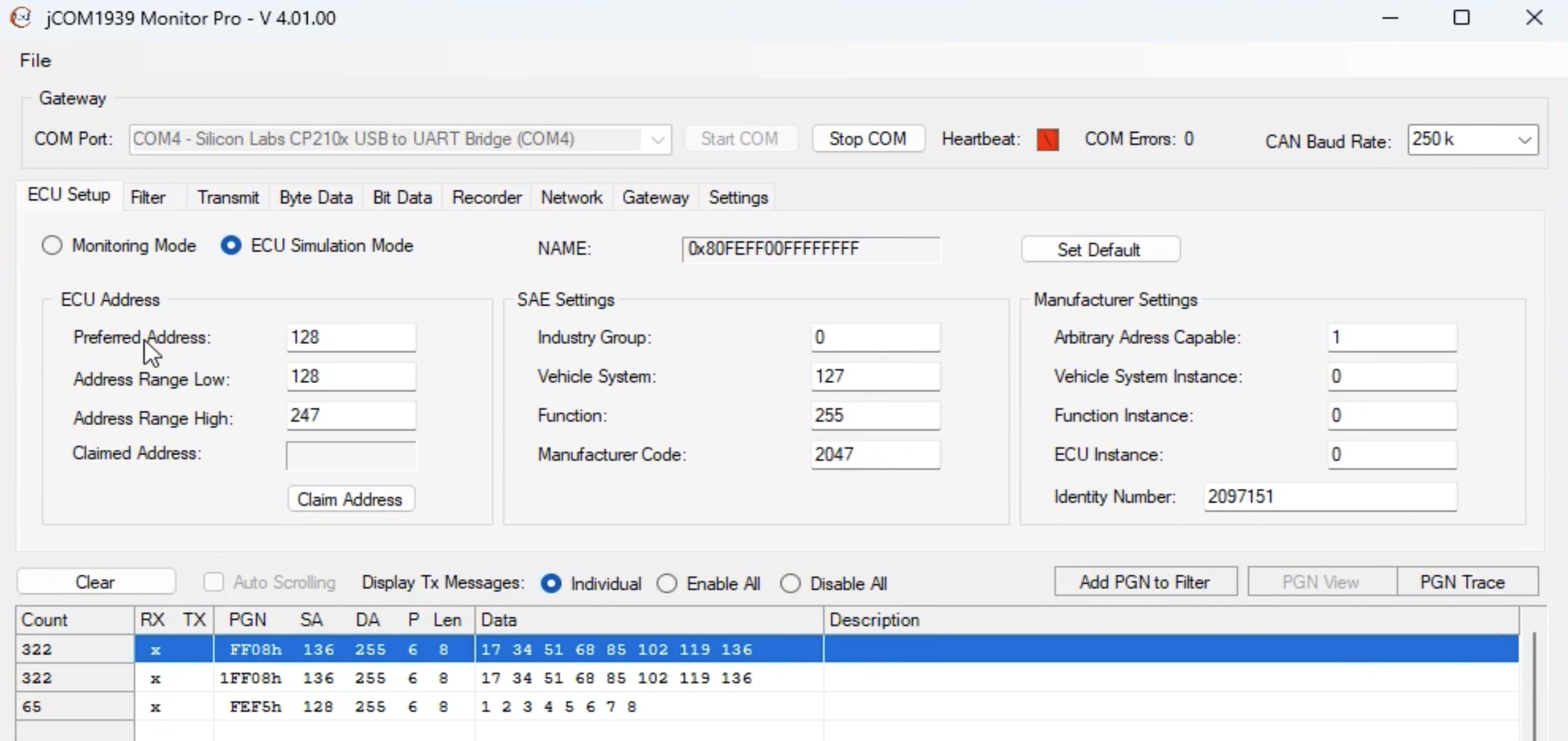
 The JCOM1939 Monitor Software is a specialized tool designed to interface with and monitor data on the SAE J1939 communication network. SAE J1939 is a standardized protocol commonly used in heavy-duty vehicles, agriculture equipment, and industrial machinery for onboard diagnostics and data communication. This essay explores the features, applications, and significance of JCOM1939 Monitor Software in modern industries.
Overview of JCOM1939 Monitor Software
The JCOM1939 Monitor Software serves as a critical diagnostic and analysis tool, enabling users to decode, visualize, and troubleshoot data transmitted across a J1939 network. Typically designed to interface with J1939-capable hardware modules via physical connectors like CAN (Controller Area Network) interfaces, the software provides a user-friendly platform for analyzing complex data streams.
This software is tailored to meet the demands of engineers, technicians, and developers working with heavy machinery and vehicles. It supports monitoring and analysis of key J1939 parameters, including Parameter Group Numbers (PGNs), Source Addresses (SA), and Data Length Codes (DLC).
Key Features
- Data Visualization:
The software provides real-time data visualization, offering users clear insights into network traffic. It often includes features like graphical representations of data trends and message logs, which simplify complex analysis tasks. - Filtering and Logging:
JCOM1939 Monitor Software enables users to filter data based on specific PGNs, source addresses, or other parameters. It also supports logging data for further analysis, a feature critical in identifying recurring issues or for compliance with reporting standards. - Diagnostic Trouble Code (DTC) Analysis:
One of the standout features is its ability to decode and interpret DTCs. These codes are essential for identifying faults within a vehicle's system, enabling efficient troubleshooting and maintenance. - Customizability:
Many versions of the software allow users to configure settings to match specific network requirements. Custom filters, triggers, and alerts can be set up to streamline the diagnostic process. - User-Friendly Interface:
The software is designed with an intuitive interface, often including drop-down menus, drag-and-drop functionality, and well-organized tabs to simplify navigation, even for less experienced users.
Applications
JCOM1939 Monitor Software is indispensable in several industries, particularly those reliant on heavy machinery and vehicles. Examples include:
- Automotive Diagnostics:
Engineers use the software to analyze and troubleshoot communication between various electronic control units (ECUs) within vehicles. - Fleet Management:
Fleet operators leverage J1939 monitoring tools to ensure optimal performance, reduce downtime, and conduct preventative maintenance across a fleet of vehicles. - Agriculture and Construction Equipment:
Monitoring data on machinery like tractors and excavators helps operators optimize efficiency and detect potential failures before they become critical. - Research and Development:
Developers working on vehicle systems or aftermarket equipment utilize the software for testing, ensuring compatibility with J1939 protocols.
Importance of JCOM1939 Monitor Software
The JCOM1939 Monitor Software plays a pivotal role in maintaining the reliability and efficiency of systems that depend on the J1939 protocol. By simplifying complex data monitoring and interpretation, the software reduces the time and effort required for diagnostics, minimizes equipment downtime, and helps ensure compliance with industry standards.
Moreover, the ability to log and analyze data fosters a proactive approach to maintenance. Early detection of anomalies leads to cost savings and enhances safety by preventing catastrophic equipment failures.
Conclusion
In the evolving landscape of industrial and vehicular technology, tools like the JCOM1939 Monitor Software are indispensable. Its robust features, ease of use, and adaptability make it a cornerstone for professionals tasked with maintaining and optimizing J1939-based systems. As technology advances, we can expect further enhancements in such monitoring tools, cementing their role in ensuring operational excellence across various industries. More Information...
SAE J1939 Starter Kit and Network Simulator
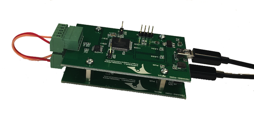
Our JCOM.J1939 Starter Kit and Network Simulator was designed to allow experienced engineers and beginners to experiment with SAE J1939 data communication without needing to connect to a real-world J1939 network, i.e., a diesel engine.
To establish a network, you need at least two nodes. This applies especially to CAN/J1939, where the CAN controller will shut down after transmitting data without receiving a response. Therefore, our jCOM.J1939 Starter Kit and Network Simulator consist of two J1939 nodes: our jCOM.J1939.USB, an SAE J1939 ECU Simulator Board with USB Port. More Information...
USB-CAN PC Interface with SAE J1939-13 Type II Connector
The Leaf Light HS v2 J1939-13 Type II, a standout in Kvaser's Leaf Light product series, is renowned for its reliability and affordability in connecting any CAN network to a PC or mobile computer. It's not just a workhorse but a dependable and cost-effective solution. The Leaf Light HS v2 J1939-13 Type II is a device that [...]
Arduino-Due-Based SAE J1939 Programming Kit - Quick Start Reference
Unleash the power of the Arduino Due with ARM Cortex-M3 processor to develop and test your SAE J1939 application, may it be an SAE J1939 to USB protocol converter, an SAE J1939 Bridge, an SAE J1939 data monitor, and many more. The SAE J1939 Programming Kit comes with many programming samples, including a full-blown SAE J1939 [...]
 Loading... Please wait...

