Blog
Recent Posts
Mastering CAN Bus: Essential Guide to Understanding and Troubleshooting Vehicle Networks
Posted by on
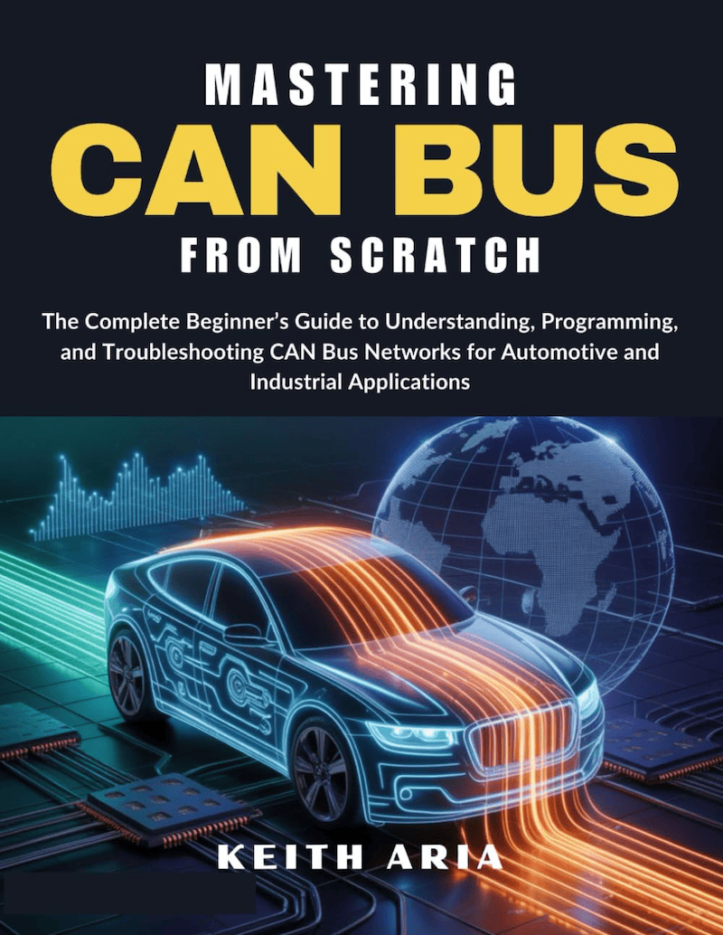
 In today’s world of connected vehicles and industrial automation, understanding the details of networked communication protocols has become a pivotal skill for engineers and technicians alike. The book Mastering CAN Scratch: Understanding & Troubleshooting (ISBN/ASIN B0G24Z25RZ) steps into this space by offering a comprehensive, hands-on guide to the widely used Controller Area Network (CAN) bus and its associated troubleshooting methodologies. It takes the reader from the fundamentals—what a CAN bus is, how it physically and logically operates, typical wiring and bus architectures—through to more advanced diagnostic techniques including fault isolation, signal integrity issues, node conflicts and data error conditions. What makes it stand out is its “scratch-from-first-principles” approach: rather than assuming prior mastery, the author invites you to build your understanding from the ground up, making it suitable for both newcomers and seasoned professionals looking to refresh or expand their CAN bus troubleshooting toolkit.
What truly elevates the book is its real-world orientation. Rather than purely theoretical descriptions, it includes case studies and practical workflows: how to detect bus conflicts using oscilloscopes, how to interpret error-frames under different fault conditions, how to systematically approach intermittent/cold-start faults and how to modify or validate node firmware settings to eliminate elusive problems. The author also dedicates attention to emerging variants and enhancements of the CAN protocol—so you’re not just learning “old school” classical CAN, but gaining insight into how to troubleshoot modern implementations that may incorporate CAN FD, higher bit-rates, and complex multi-ECU networks. For anyone working in vehicle diagnostics, embedded system design or industrial control networks, this book is a valuable addition to the reference shelf—and, with its clear writing and structured progression, a very practical learning resource. More information...
 ESP32S3 Board with CAN FD and Classical CAN Ports
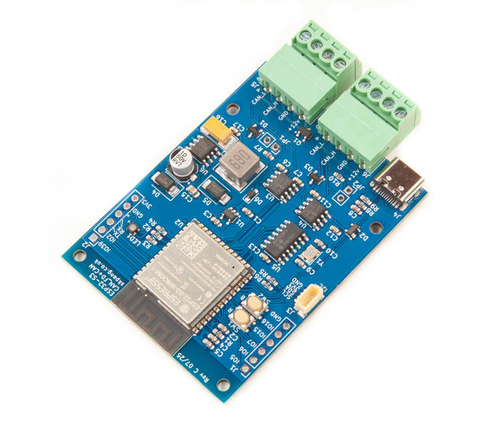
The board is built around the ESP32-S3‑WROOM‑1‑N8R8 module, giving it Wi-Fi, Bluetooth 5 (including LE and mesh) and a dual-core Xtensa® 32-bit LX7 processor up to 240 MHz. It also packs 8 MB of quad-SPI flash and 8 MB of PSRAM, making it capable of fairly heavy embedded workloads. On the connectivity side, this board supports classical CAN (Controller Area Network) via the ESP32-S3’s built-in CAN controller, and extends to CAN FD (Flexible Data-rate) using an external MCP2518FD SPI-based controller plus high-speed CAN transceivers. The board is powered by a 7 V–24 V input through an onboard SMPS with reverse-polarity protection, features a USB-C connector for power and native USB OTG programming/debugging, and includes convenient extras like boot/reset buttons, an I²C expansion port, and an RGB LED for status indication.
From an application standpoint, the board is tailored for scenarios where robust in-vehicle or industrial networking meets wireless/edge processing. Because it supports both classical CAN and CAN FD, it is well-suited for bridging legacy CAN networks with next-generation high-bandwidth CAN FD systems — for instance, automotive diagnostics, industrial automation gateways, or IoT devices that aggregate sensor data via CAN and then upload it wirelessly via Wi-Fi or BLE. The native USB support simplifies programming and debugging compared to boards that require a separate USB-UART chip. In short, it presents a flexible platform for embedded engineers working at the intersection of networked control buses and wireless edge intelligence. More information...
Classical CAN vs. CAN FD in Automotive, Medical Devices & Robotics – Key Differences and Usage
Controller Area Network (CAN) is a robust serial bus widely used in embedded systems across industries like automotive, medical devices, and robotics. “Classical” CAN (the original CAN 2.0 standard) has served reliably for decades in vehicle ECUs, industrial machines, and more. However, modern systems demand higher data throughput and efficiency than classical CAN’s 1 Mbit/s [...]
Harnessing the Power of the ESP32-S3: A Look at Copperhill’s CAN FD Development Board
In the evolving landscape of IoT, industrial automation, and automotive communication, the demand for a versatile, wireless-enabled microcontroller with CAN bus capabilities has never been greater. Copperhill Technologies rises to the occasion with its latest innovation—a development board based on the ESP32-S3-WROOM-1-N8R8, engineered to support both Classical CAN and CAN FD protocols. At the heart of [...]
The Teensy Series of Processor Modules: A Versatile Platform for Embedded Systems
The Teensy series of processor modules is a family of compact, high-performance microcontroller boards developed by PJRC. These boards are widely recognized for their small form factor, powerful processing capabilities, and extensive I/O support, making them an ideal choice for a variety of embedded systems applications, including robotics, audio processing, and IoT (Internet of Things) [...]
Embedded CAN Bus Development with the ESP32 Processor
The Controller Area Network (CAN) bus is a robust communication protocol designed to facilitate data exchange between microcontrollers and devices in automotive and industrial applications. With its high reliability and real-time capabilities, it has become a cornerstone in modern embedded systems. The ESP32, a popular microcontroller from Espressif Systems, offers integrated CAN controller support, making [...]
Embedded Systems Development for NMEA 2000
Embedded systems development for the NMEA 2000 (National Marine Electronics Association) protocol presents unique challenges and opportunities in the field of marine electronics. NMEA 2000 is a standardized communication protocol designed to enable robust and reliable data exchange among marine instruments and devices. This essay explores the fundamental aspects of developing embedded systems for NMEA [...]
JCOM1939 Monitor Software - A Critical SAE J1939 Diagnostic and Analysis Tool
The JCOM1939 Monitor Software is a specialized tool designed to interface with and monitor data on the SAE J1939 communication network. SAE J1939 is a standardized protocol commonly used in heavy-duty vehicles, agriculture equipment, and industrial machinery for onboard diagnostics and data communication. This essay explores the features, applications, and significance of JCOM1939 Monitor Software in [...]
ESP32 Processor: CAN Bus Topology and Termination Resistors
This post is an excerpt from our application note Controller Area Network (CAN) Development with ESP32. It is my experience that newcomers to the technology overlook the importance of termination resistors. Missing or misplaced resistors can lead to transmission errors or even prevent transmission altogether. The general rule is that if you connect to an existing, fully [...]
ESP32 Processor: Adding CAN/CAN-FD Controllers per SPI Port
This post is an excerpt from our application note Controller Area Network (CAN) Development with ESP32. The internal CAN controller SJA1000 does not support CAN-FD and is not CAN-FD tolerant. To use CAN-FD with the ESP32, you need to employ CAN-FD breakout boards that are accessible per the ESP32’s SPI ports. Note: The SPI ports are not [...]
ESP32 Processor: Adding a CAN Bus Transceiver
This post is an excerpt from our application note Controller Area Network (CAN) Development with ESP32.As a quick reference, I want to address the need for a CAN transceiver. As mentioned in the previous chapter, the ESP32 has an internal CAN Bus controller. However, this doesn't mean you can directly connect it to a network. You [...]
 Loading... Please wait...
