 Loading... Please wait...
Blog
Recent Posts
SAE J1939 Data Traffic Generator For Diesel Engine Network Simulation
Posted by on
I am writing this post to respond to multiple inquiries from newcomers to the SAE J1939 technology. Most questions are like, "Can your device simulate any PGN, for instance, engine speed in rpm?" or "Can your device simulate a 2014 Tonka Flex diesel engine?" The short answer is yes, but things are a bit more complex.
First, PGNs are not only used for data transmission; they also manage diagnostics and protocol management. Our systems support any PGN data frame and use the protocol features to simulate an SAE J1939 node. Second, our devices and simulation software do not simulate specific diesel engines. SAE J1939 is a generic protocol for diesel engines, and the user can set up a collection of PGNs that simulates a particular engine as closely as possible.
I will provide a few examples of how the simulation works in the following. For a full explanation of our Windows software, please refer to the J1939Monitor Software User Manual.
Also, please be aware that you will need one of our SAE J1939 boards to physically connect to an SAE J1939 network while the Windows software manages the actual simulation. They are:
- SAE J1939 Gateway Module with USB Port, RTC, MIcroSD Memory Card...
- SAE J1939 Gateway with USB Port, RTC, MicroSD, Power Supply...
But let’s make this a point: When developing and testing your application, you will need a J1939 network. A single node connected to your device will not do. A working network provides J1939 operation under stable conditions, i.e., the assurance that any possible communication problems have to do with your device (no pun intended; that’s just in the nature of things).
In this case, we recommend our SAE J1939 Starter Kit and Network Simulator:
After this lengthy introduction, let's have a look at the simulation setup.
SAE J1939 Data Monitoring
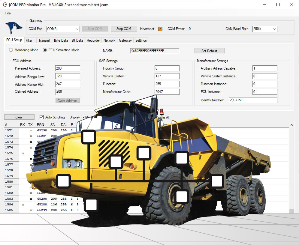
Data Monitoring represents the first (and easy) step in connecting to an SAE J1939 network. While using our J1939 Monitor Software, switch to the "Filter" section and click "Pass All." Assuming you are connected to the physical network, you should see data flowing.
SAE J1939 Data Transmission
However, if you want to transmit SAE J1939 data (PGNs), you need to claim a node address.
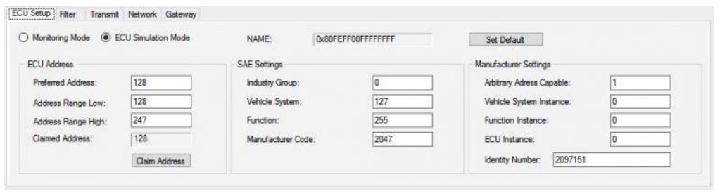
This section is where you configure an SAE J1939 ECU through parameters such as Preferred Node Address, Negotiable Address Range, and the NAME setup. If you are not sure how to set the parameters, simply go with the default parameters. They are set up to have the ECU operate on the safe side without interfering with your J1939 network.
![]()
This section allows you to edit any PGN. However, please be aware which PGN you use. The point is, don't use a random number. You might assign a PGN used for protocol management and that may result in unforeseen results.
The program allows you to assign a message frequency or sending a message manually.
SAE J1939 Simulation of Digital Signals
The Bit Data section was designed with the modification of digital signals in mind. The program uses check boxes to set or reset digital information. The following screenshot demonstrates how several bits in one PGN were modified:
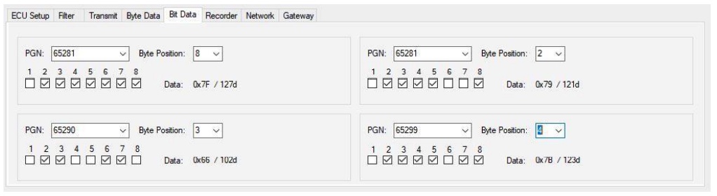
The result is automatically transmitted into the SAE J1939 network.
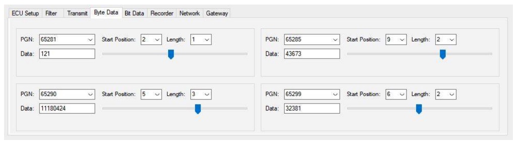
SAE J1939 Simulation of Analog Signals
In the Byte Data section of the jCOM1939Monitor software, the user can select a previously designed PGN, the data start position, and the data length (1, 2, 3, or 4 bytes). The program will display the data as selected and allows the user to modify the data either per text input or sliding the associated track bar.
This mode was specifically designed with simulation of analog signals in mind. However, due to the generic nature of the software, it does not verify that the selected PGN data represents an analog parameter. In the above sample, we chose a random selection of proprietary PGNs, and, while the screen shows four different PGNs, the program also allows the simultaneous modification of several bytes in the PGN data field.
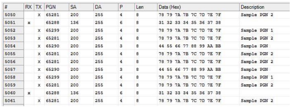
The following screenshot demonstrates how bytes in various PGNs were modified:
More Information
The information in this post can only be rudimentary, since the purpose was to provide a quick overview on how our hardware and software simulates an SAE J1939 network.
For detailed information on the J1939 Monitor Software, please see:
In addition, we have invested great efforts and time to create more helpful information for the newcomer as well as the experienced user:
- A Beginner's Guide to SAE J1939 Embedded Software Development...
- Simulating SAE J1939 PGNs Used By Truck & Bus FMS (Fleet Management System) Standard...
- SAE J1939 Monitor Software - Setting Up PGN Simulation Such As Engine Coolant Temperature...,
- SAE J1939 Simulator Generates Frequently Used SAE J1939 Signals (PGNs) For Diesel Engines...
A Comprehensible Guide to J1939

SAE J1939 has become the accepted industry standard and the vehicle network technology of choice for off-highway machines in applications such as construction, material handling, and forestry machines. J1939 is a higher-layer protocol based on Controller Area Network (CAN Bus).
It provides serial data communications between microprocessor systems (also called Electronic Control Units - ECU) in any kind of heavy duty vehicles. The messages exchanged between these units can be data such as vehicle road speed, torque control message from the transmission to the engine, oil temperature, and many more.
The information in this book is based on two documents of the SAE J1939 Standards Collection: J1939/21 - Data Link Layer J1939/81 - Network Management A Comprehensible Guide to J1939 is the first work on J1939 besides the SAE J1939 standards collection.
It provides profound information on the J1939 message format and network management combined with a high level of readability.