Blog
Recent Posts
Galvanically Isolated CAN Bus Transceivers Protect Networks Against Destructive Energy
Posted by on

High noise levels on a CAN bus network have the potential to destroy CAN bus transceivers. This noise originates mainly from two sources, ground loops and electrical line surges.
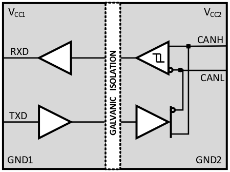
Protecting a network against this destructive energy requires the galvanic isolation of the CAN bus system from other local node circuitry.
For more information on Controller Area Network, see A Brief Introduction to Controller Area Network.
CAN Bus Cabling & Termination
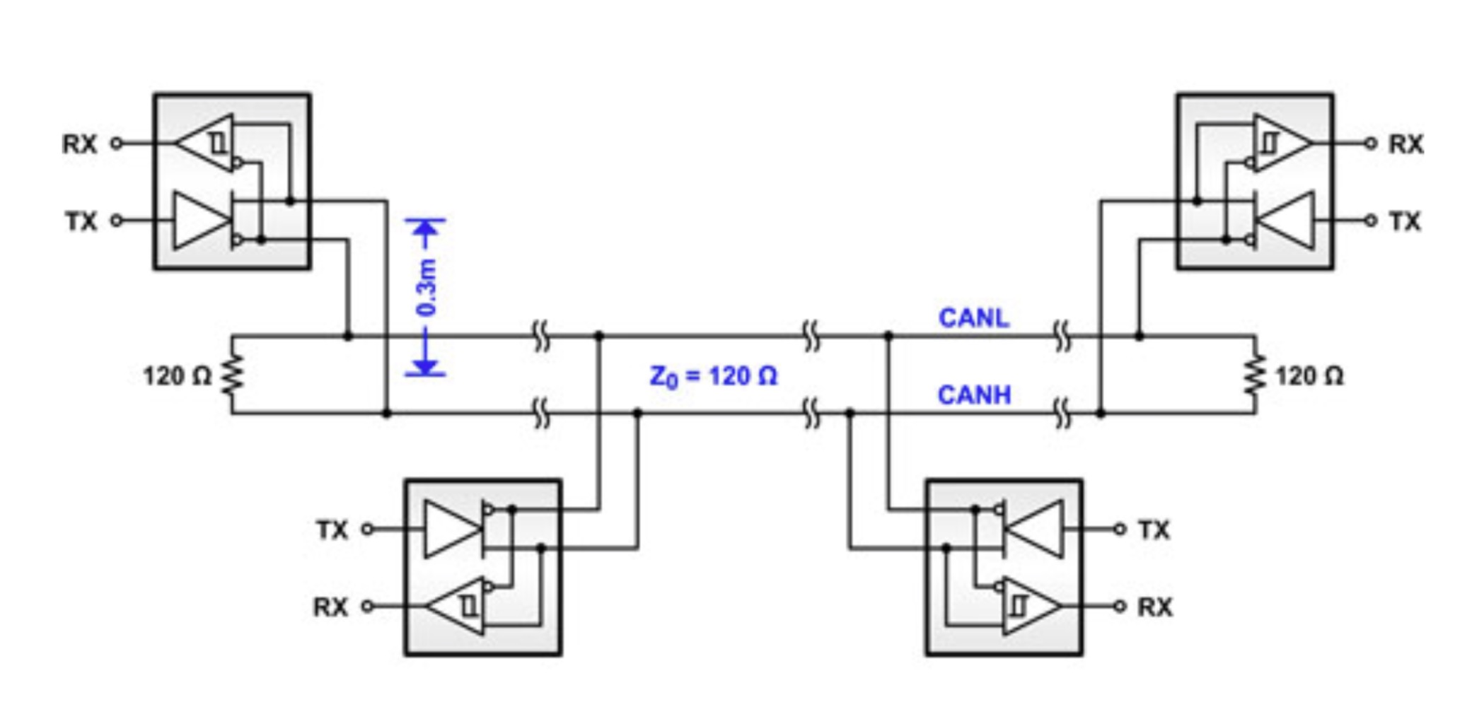
The CAN Bus specification ISO11898 calls for the use of twisted cable, shielded or unshielded, with a characteristic cable impedance of Z0 = 120 Ohm nominal. Thus, an industrial cable, e.g., an RS485 cable, is satisfactory for CAN Bus applications.
Every CAN bus must be terminated with resistors of RT = 120 Ohm at each end of the network to assure minimum reflections. Stubs, basically representing unterminated line branches, should be maintained as short as possible, but must not exceed 0.3 meters (~ 1 foot) in length.

Typical CAN Bus Network
Note: A CAN bus structure is not limited in terms of network architecture, thus not every network structure may turn out as straight-forward as demonstrated in the above image. Consequently, the determination of "network end" may be difficult and may require some experimenting.
Galvanic Isolation
Ground loops happen when bus node circuits at distant locations use their local ground as a reference potential. In this case, signal return currents cannot flow back to the ground potential of the sourcing driver on a direct path. Instead, they are forced to return via the complex ground network of the electrical installation and, thus, become receptive to directly coupled, high switching currents.
Connecting multiple local grounds directly through a ground wire makes matters worse. Because these grounds frequently maintain significant differences in voltage levels, a low-impedance ground wire causes high, unintended compensation currents to flow, which may damage components.
Electrical surges are habitually the result of inductive-coupled currents into the network cable. In particular, long cable runs are highly susceptible to these surges as the cable might pass electrical equipment switching large currents or might run close to high-current carrying conductors.
Other surges include electrostatic discharges (ESD) caused by individuals during installation and maintenance work, or by direct or indirect lightning strikes.
Isolated CAN Bus Transceiver
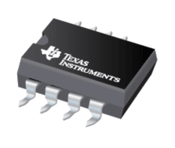
The ISO1050 by Texas Instruments (as utilized in our PiCAN2 Duo Isolated CAN-Bus Board for Raspberry Pi) is a galvanically isolated CAN Bus transceiver that matches the specifications of the ISO11898-2 standard. The device comes with logic input and output buffers separated by a silicon oxide (SiO2) insulation barrier providing galvanic isolation of up to 5000 VRMS for ISO1050DW and 2500 VRMS for ISO1050DUB. In combination with isolated power supplies, the device prevents noise currents on a CAN Bus or other circuits from entering the local ground and interfering with or destroying sensitive circuitry.
As a CAN Bus transceiver, the device implements differential transmit capability into the bus and differential receive capability to a CAN Bus controller at signaling rates up to 1 megabit per second (Mbps). The device operates in especially harsh environments, and it features cross-wire, overvoltage, and loss of ground protection from –27 V to 40 V and over-temperature shutdown, as well as –12-V to 12-V common-mode range.
The ISO1050 is suitable for operation within an ambient temperature range of –55°C to 105°C.
More Resources
- Isolate your CAN systems without compromising on performance or space...
- Isolated CAN Reference Design...
- Isolated CAN solution by using ISO1050 and SN6501...
Isolated CAN FD Breakout Board
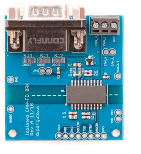
This is an isolated CAN Bus breakout board with Flexible Data Rate using the Analog Devices ADM3055E IC with a data rate of up to 12 Mbps. The output pins are on both screw terminals and a DB9 connector.
The DB9 connector an be configured for use with an OBDII cable, SAE J1939 cable, or CAN Analyser pin-out via solder bridges.
Features
- 5 VDC supply requirement
- Vio 1.7 VDC to 5.5 VDC logic levels
- ISO 11898-2:2016 compliant (CAN FD)
- Data rates up to 12 Mbps for CAN FD
- Low maximum loop propagation delay: 150 ns
- Extended common-mode range: ±25 V
- Bus fault protection: ±40 V on CANH and CANL pins
- Low power standby support remote wake request
- 5 kV rms/3 kV rms signal and power isolated CAN transceivers
- isoPower integrated isolated DC-DC converter
 Loading... Please wait...


