Blog
Recent Posts
ESP32 Processor: Adding a CAN Bus Transceiver
Posted by on
This post is an excerpt from our application note Controller Area Network (CAN) Development with ESP32.
As a quick reference, I want to address the need for a CAN transceiver. As mentioned in the previous chapter, the ESP32 has an internal CAN Bus controller. However, this doesn't mean you can directly connect it to a network. You will need a line driver (transceiver) to convert the controller’s TTL signal to the actual CAN level, which is a differential voltage that the ESP32 cannot provide. The use of differential voltage significantly enhances the reliability of CAN on a hardware level.
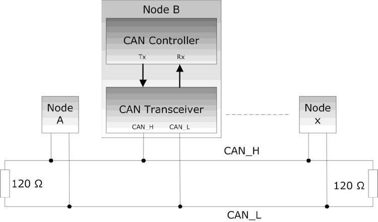
The next image compares both signals, TTL and differential voltage:
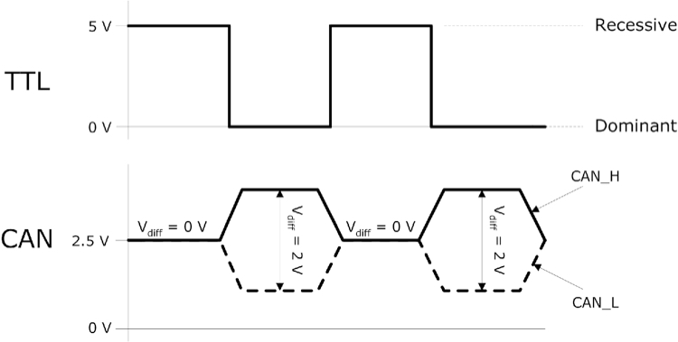
The actual signal status, recessive or dominant, is based on the differential voltage between CAN_H and CAN_L (2V during dominant bit time; 0V during recessive bit time).
As with many other ESP32 hardware features, the CAN controller output (CAN_TX, CAN_RX) can be assigned to almost any GPIO. In the following, we assume GPIO25 (CAN_TX) and GPIO26 (CAN_RX), which appear to be virtual industry standards.
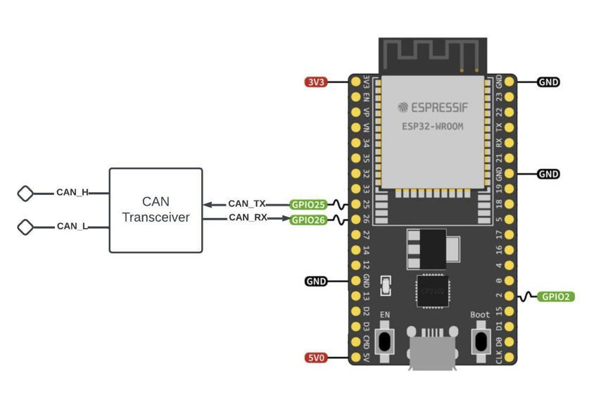
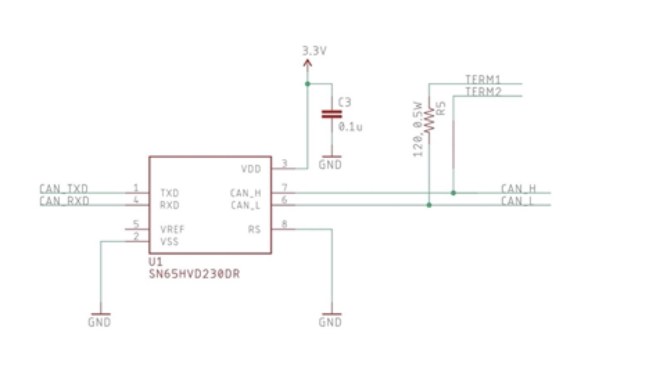
The following image shows a schematic utilizing the popular SN65HVD CAN transceiver:
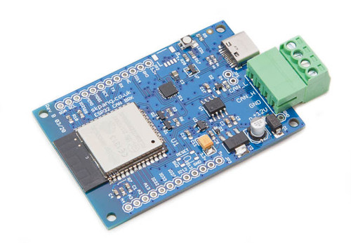
ESP32 WiFi, Bluetooth Classic, BLE, CAN Bus Module
This board has an onboard ESP32 WROOM-32 WiFi, Bluetooth Classic, BLE Module, and a CAN Bus port with a transceiver. Also onboard are an RGB LED and IO pins on a 0.1" pad.
Programming is accomplished through the popular Arduino IDE connected to the USB-to-Serial converter with a USB-C connector, automatic bootloader, and reset. The ESP32 is a low-cost, low-power system-on-chip microcontroller with integrated Wi-Fi and dual-mode Bluetooth. It employs a Tensilica Xtensa LX6 microprocessor in dual-core and single-core variations.
It includes built-in antenna switches, RF baluns, a power amplifier, a low-noise receive amplifier, filters, and power management modules. More Information...
Classical CAN (CC), the Original CAN Bus Technology
This post is an excerpt from our application note Controller Area Network (CAN) Development with ESP32. Note: The term “Classical CAN” was introduced in the ISO 11898-1: 2016 Standard. Classical CAN represents the basis for CAN FD (and CAN XL), meaning they share the same features and advantages, as explained in the previous chapter. While CAN FD adds [...]
Controller Area Network (CAN Bus) - Physical Layer And Bus Topology
The following is an excerpt from A Comprehensible Controller Area Network by Wilfried Voss. The ISO/OSI Reference Model specifies seven levels starting with the physical connection up to the actual user application, i.e., the Application Layer. The standard CAN Bus implementation neglects the connection between the Data Link Layer and the Application Layer to save on relevant memory resources [...]
Galvanically Isolated CAN Bus Transceivers Protect Networks Against Destructive Energy
High noise levels on a CAN bus network have the potential to destroy CAN bus transceivers. This noise originates mainly from two sources, ground loops and electrical line surges.Protecting a network against this destructive energy requires the galvanic isolation of the CAN bus system from other local node circuitry. For more information on Controller Area [...]
 Loading... Please wait...

