Blog
Recent Posts
Embedded CAN Bus Development with the ESP32 Processor
Posted by on
 The Controller Area Network (CAN) bus is a robust communication protocol designed to facilitate data exchange between microcontrollers and devices in automotive and industrial applications. With its high reliability and real-time capabilities, it has become a cornerstone in modern embedded systems. The ESP32, a popular microcontroller from Espressif Systems, offers integrated CAN controller support, making it a compelling choice for implementing CAN bus systems. This essay explores the development process of a CAN bus using the ESP32 processor.
Overview of CAN Bus
The CAN protocol, standardized as ISO 11898, was developed to address the need for reliable communication in noisy environments, particularly in automotive systems. It employs a multi-master, message-oriented architecture and uses differential signaling to reduce susceptibility to noise. CAN is highly efficient, capable of handling data rates up to 1 Mbps (Classical CAN) and beyond with the advent of CAN FD (Flexible Data Rate).
Why ESP32 for CAN Bus Development?
The ESP32 is a versatile microcontroller featuring dual-core processing, Wi-Fi, and Bluetooth capabilities. One of its lesser-known features is the integrated SJA1000-compatible CAN controller. When paired with an external CAN transceiver, such as the MCP2551 or TJA1050, the ESP32 can interface seamlessly with CAN networks. The combination of processing power, connectivity options, and cost-effectiveness makes the ESP32 ideal for developing modern CAN-based applications.
Steps for Developing a CAN Bus System with ESP32
- Hardware Setup:
- ESP32 Board: Select an ESP32 development board, such as ESP32 DevKit or NodeMCU.
- CAN Transceiver: Use an external CAN transceiver module to convert the ESP32’s logic-level signals to differential signals required by the CAN bus.
- Connections: Connect the ESP32's CAN controller pins (RX and TX) to the transceiver. Ensure proper termination resistors (typically 120 Ω) are in place on the CAN bus to maintain signal integrity.
- Software Configuration:
- Install the ESP-IDF (Espressif IoT Development Framework) or Arduino IDE with the necessary libraries for CAN communication.
- Use libraries like
ESP32CANor the native CAN driver provided in ESP-IDF.
- Programming:
- Initialize the CAN controller with appropriate baud rates, filters, and operating modes (e.g., Normal, Listen-Only, or Loopback).
- Write functions to send and receive CAN messages. Each message consists of an identifier, data length code (DLC), and data payload.
- Testing and Debugging:
- Use a CAN analyzer tool to monitor the bus and validate communication.
- Debug issues by checking electrical connections, analyzing timing errors, and verifying message configurations.
- Integration with Applications:
- Implement logic to process received messages and trigger actions based on application requirements.
- Use the ESP32’s connectivity features to bridge CAN data with other networks (e.g., Wi-Fi or Bluetooth).
Example Application: Vehicle Diagnostics
One practical application of the ESP32 with CAN bus is On-Board Diagnostics (OBD-II) for vehicles. By connecting the ESP32 to a vehicle’s CAN network via the OBD-II port, users can monitor engine parameters, read diagnostic trouble codes (DTCs), and send commands to the Electronic Control Unit (ECU). Additionally, the ESP32 can transmit this data over Wi-Fi to a smartphone app, providing a user-friendly interface for vehicle diagnostics.
Challenges and Solutions
- Noise and Interference: Use proper shielding and grounding to minimize electrical noise.
- Synchronization Issues: Ensure accurate timing configurations for the CAN controller to avoid synchronization errors.
- Compatibility: Verify compatibility between the ESP32, transceiver, and the existing CAN network.
Future Prospects
With the increasing adoption of CAN FD and Ethernet-based communication in modern vehicles and industries, the role of flexible microcontrollers like the ESP32 will expand. Integration of advanced features such as over-the-air updates and IoT connectivity can transform traditional CAN applications into intelligent systems.
Conclusion
The development of a CAN bus system using the ESP32 processor combines the reliability of the CAN protocol with the versatility of a modern microcontroller. Whether for automotive diagnostics, industrial automation, or IoT applications, the ESP32 provides a cost-effective and scalable solution. By leveraging its features and following best practices in hardware and software design, developers can create innovative and robust systems to meet the demands of a connected world.
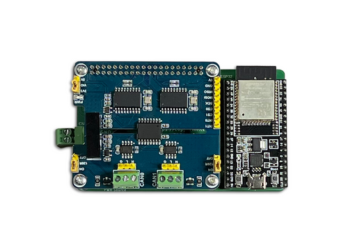
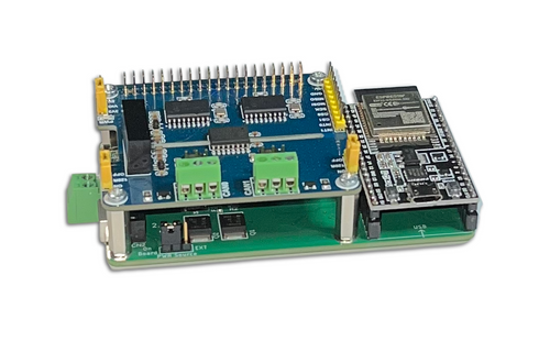
 ESP32 Development Board with Dual Isolated CAN Bus HAT
The espBerry DevBoard combines the ESP32-DevKitC development board with any Raspberry Pi HAT by connecting to the onboard RPi-compatible 40-pin GPIO header. The espBerry should not be viewed as an alternative to the Raspberry Pi but as a means of extending the ESP32’s functionality by tapping into the extensive range of RPi HATs available on the market and leveraging the many flexible hardware options.
The espBerry is an ideal solution for Internet of Things (IoT) applications, particularly those that require wireless capabilities. All open-source code samples utilize the popular Arduino IDE, which offers excellent programming features. More Information...
ESP32 Processor: Adding a CAN Bus Transceiver
This post is an excerpt from our application note Controller Area Network (CAN) Development with ESP32.As a quick reference, I want to address the need for a CAN transceiver. As mentioned in the previous chapter, the ESP32 has an internal CAN Bus controller. However, this doesn't mean you can directly connect it to a network. You [...]
CAN Bus And SAE J1939 Bus Voltage
CAN Bus MediumAccording to ISO-11898 specification, the CAN bus medium must support two logical states: Recessive and dominant. A CAN controller with its TTL output uses an additional line driver (transceiver) to provide the standard CAN Bus level. The dominant level (TTL = 0V) always overrides a recessive level (TTL = 5V), which is, especially [...]
Reference Board With Galvanically Isolated CAN Bus Transceiver Supports Bit Rates Up To 5 Mbit/s
Recom introduced their R-REF03-CAN1 Reference Board to demonstrate the ISO1042 isolated CAN Bus transceiver in combination with the R1SX-3.305/H isolated DC/DC converter. The reference board requires only a single 3.3 VDC external power supply. A green LED indicates the presence of the VCC2 supply on the secondary (CAN Bus) side. The reference board enables designers to develop [...]
Isolated CAN Transceiver With 70-V Bus Fault Protection and Flexible Data Rate (CAN FD)
Texas Instruments (TI) has introduced two more CAN Bus transceivers. They offer ±70-VDC bus-fault protection and ±30-V common-mode voltage range. The ISO1042 and ISO1042-Q1 help engineers protecting low-voltage circuits and increase communication bandwidth in industrial applications such as grid infrastructure, motor drives and building automation, as well as hybrid electric vehicles and electric vehicles (HEVs/EVs). Used in conjunction [...]
CAN Bus Transceiver Modules With Isolated DC/DC Converter In One Module
Mornsun CAN Bus transceiver modules replace the traditional design by integrating transceiver, isolation chip, and high efficient DC/DC isolated power in one module. The modules can be used for inter-communications between devices on the industrial bus, achieving the signal transmission and power isolation. They target the automotive industry, rail transportation, smart monitoring, smart meters, and more.Mornsun [...]
 Loading... Please wait...
