 Loading... Please wait...

Blog
Recent Posts
Arduino Due Dual CAN Bus Development Platform for Rapid CAN Bus and SAE J1939 Prototyping
Posted by on
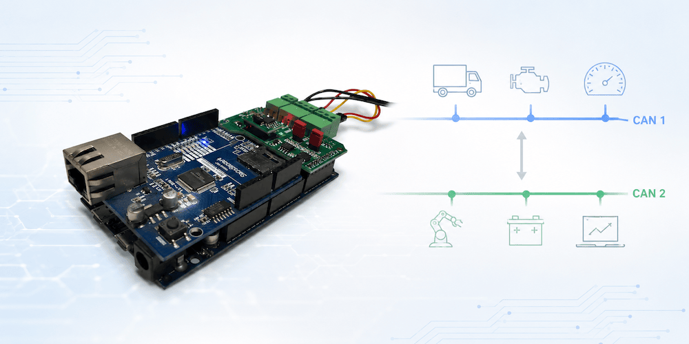 One of the biggest obstacles in CAN bus development is not understanding the CAN protocol itself—it is finding a development platform that lets you move from an idea to a working prototype without spending weeks configuring hardware, writing low-level drivers, or debugging interface electronics.
Whether you are developing an automotive controller, an industrial CAN node, an OBD-II application, or an SAE J1939 ECU, the goal is usually the same: prove the concept quickly and then concentrate on the application itself.
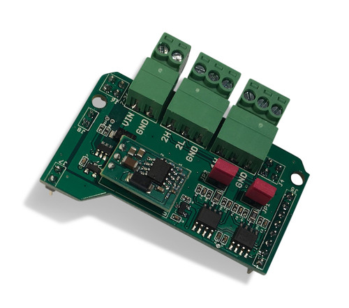 That is precisely where the Dual CAN Bus Interface for Arduino Due with Extended Power Range excels.
Unlike generic CAN modules that require additional hardware, complicated wiring, or external CAN controllers, this interface takes full advantage of the Arduino Due’s two built-in CAN controllers. The board simply adds the required CAN transceivers while providing a clean, professional interface to two independent CAN networks. Combined with the Arduino Due’s 32-bit ARM Cortex-M3 processor running at 84 MHz, the result is a remarkably powerful embedded development platform that remains easy to understand and easy to program.
More Than Hardware—A Complete Development Platform
Many embedded development boards stop at providing the hardware. After that, developers are largely on their own.
The Arduino Due platform supported by Copperhill Technologies takes a different approach.
Over the years, an extensive collection of application examples, software libraries, and complete source code has been developed specifically for CAN bus applications. Instead of beginning with a blank project, engineers can start with working software and adapt it to their own requirements.
This dramatically shortens development time for:
- Rapid prototyping
- Proof-of-concept projects
- Laboratory testing
- Research projects
- Industrial automation
- Automotive development
- Commercial product development
In many cases, developers can have their first CAN messages transmitted within minutes instead of days.
Why the Arduino Due?
Although many newer development boards are available today, the Arduino Due continues to be one of the most practical platforms for Classical CAN development.
It offers:
- Native dual CAN controllers integrated into the processor
- 84 MHz 32-bit ARM Cortex-M3 CPU
- 512 KB Flash memory
- 96 KB SRAM
- Large number of digital and analog I/O
- Mature Arduino software ecosystem
- Excellent debugging support
- Simple USB programming
Unlike SPI-based CAN shields, there is no external CAN controller that consumes processor time or complicates the software architecture. The processor communicates directly through its integrated CAN peripherals, providing a cleaner and more efficient design.
Designed for Real-World Installations
One feature that is often overlooked is the board’s extended power input range of 7 to 36 VDC.
Instead of powering the Arduino through USB or an external regulator during development, the complete system can be powered directly from many industrial and automotive power sources.
This makes it particularly attractive for:
- Heavy-duty vehicles
- Agricultural equipment
- Construction machinery
- Marine electronics
- Industrial control systems
- Mobile laboratory equipment
The board also provides jumper-selectable CAN termination resistors and activity LEDs for both CAN channels, making troubleshooting considerably easier during development.
A Library of Ready-to-Run Applications
Perhaps the greatest advantage of the platform is the large collection of proven software examples that accompany it.
These are not merely “Hello World” demonstrations—they solve real engineering problems.
Dual CAN Port Applications
Learn how to configure and operate both CAN controllers simultaneously. These examples provide an excellent starting point for applications requiring communication with two independent CAN networks.
OBD-II Libraries
Develop diagnostic tools, vehicle monitors, and automotive data acquisition systems using readily available OBD-II interfaces.
ARD1939 SAE J1939 Protocol Stack
For engineers developing heavy-duty vehicle applications, the ARD1939 protocol stack provides a practical implementation of the SAE J1939 protocol.
Rather than studying hundreds of pages of the standard before writing code, developers can work from functioning software examples and build their understanding through practical implementation.
The ARD1939 stack also serves as the foundation for numerous programming examples that demonstrate address claiming, PGN transmission, transport protocol handling, diagnostics, and other essential J1939 functions.
CAN Data Traffic Simulation
No vehicle available?
No problem.
The CAN traffic simulation examples generate realistic CAN traffic, allowing developers to test applications entirely on the workbench before connecting to real hardware.
This capability is invaluable during early software development and automated testing.
CAN Bus Bridge
One of the most popular application examples demonstrates how to connect two independent CAN networks.
Possible uses include:
- Message filtering
- Message translation
- Baud-rate conversion
- Gateway development
- Data logging
- Network isolation
Since the Arduino Due features two native CAN controllers, bridge applications become surprisingly straightforward to implement.
SAE J1939 GPS Application
Another example illustrates how GPS position data can be converted into standard SAE J1939 messages, allowing GPS information to be transmitted directly onto a heavy-duty vehicle network.
This project demonstrates how easily additional sensors and peripherals can be integrated into J1939 systems.
J1939 Baud Rate Converter
Many real-world systems must communicate between 250 kbps and 500 kbps J1939 networks.
Instead of designing such a gateway from scratch, developers can begin with a working reference implementation and customize it to meet their specific requirements.
Build Your Own Application Instead of Reinventing CAN
The greatest value of the platform is not the hardware itself.
It is the fact that developers do not have to begin every project from zero.
Whether your objective is to create a CAN gateway, an ECU prototype, a diagnostic tool, a CAN analyzer, a J1939 controller, or an industrial monitoring device, there is a strong chance that a closely related application example already exists.
That allows you to spend your engineering time developing your product rather than repeatedly solving the same low-level CAN communication problems.
An Ideal Platform for Learning and Professional Development
The Dual CAN Bus Interface for Arduino Due is equally suitable for experienced embedded engineers and developers entering the world of CAN bus networking.
Its straightforward hardware design, mature software ecosystem, and extensive collection of practical examples make it one of the easiest ways to understand CAN bus programming through hands-on experimentation.
Instead of reading endless protocol specifications before writing your first line of code, you can begin with proven software, observe a working system, and then extend it into your own application.
For rapid prototyping, proof-of-concept development, and even commercial embedded products, this combination of hardware, software, and practical examples provides a development environment that remains difficult to match. More information...
Developing SAE J1939 Applications with ARD1939 and Copperhill Technologies Hardware
One of the challenges of developing SAE J1939 applications is finding a protocol stack that is both affordable and flexible enough for prototyping, education, and custom embedded projects. To address this need, we developed ARD1939, a portable C++ SAE J1939 protocol stack that serves as the software foundation for many of our development projects and examples. Originally [...]
SAE J1939 Programming with Arduino – Function Calls Description
This post is part of a series about SAE J1939 ECU Programming & Vehicle Bus Simulation with Arduino. j1939.Initvoid j1939.Init(int nSystemTime);Initializes the ARD1939’s memory, baud rate settings, etc.nSystemTime - This is the loop time of your application in milliseconds. This information will provide the ARD1939 protocol stack a time base to manage all timers required for various protocol tasks.Ideally, the system [...]
SAE J1939 Programming with Arduino – Application Structure
This post is part of a series about SAE J1939 ECU Programming & Vehicle Bus Simulation with Arduino. As with every Arduino application, the initialization of data and the J1939 protocol takes place during the setup() function, while the actual application resides in loop(). setup() - The j1939.Init function is mandatory to operate ARD1939. [...]
SAE J1939 Programming with Arduino – ARD1939 Protocol Stack Reference
This post is part of a series about SAE J1939 ECU Programming & Vehicle Bus Simulation with Arduino. The functions available to the SAE J1939 application layer (i.e your program) are:Initialization j1939.Init – Initializes the protocol stack settings j1939.SetPreferredAddress – Sets the preferred node (source) address j1939.SetAddressRange– Sets the negotiable [...]
SAE J1939 Programming with Arduino – Debugging Macros
This post is part of a series about SAE J1939 ECU Programming & Vehicle Bus Simulation with Arduino. Please be aware that the following macros are one-liners. Due to the limited page space, some macros appear as wrapped into more than one line and the line breaks are indicated with “\”. SAE J1939 has become the accepted industry standard and [...]
SAE J1939 Programming with Arduino – RTS/CTS Session Test Program
This post is part of a series about SAE J1939 ECU Programming & Vehicle Bus Simulation with Arduino. Just for kicks, I extended the previously used Arduino sketch to simulate a fully functional RTS/CTS session (yet again, the code is highly tailored to the previous RTS/CTS session). Based on that sketch, I could simulate all error scenarios on the receiver’s side.This [...]
SAE J1939 Programming with Arduino – Conclusion
This post is part of a series about SAE J1939 ECU Programming & Vehicle Bus Simulation with Arduino. With all previous programming examples installed and explained, you should now have a pretty good grip on programming your own SAE J1939 application with the Arduino Uno and/or the Mega 2560.Yet, there are still numerous, possible scenarios for J1939 applications and all [...]
SAE J1939 Programming with Arduino – ARD1939 Sample Application
This post is part of a series about SAE J1939 ECU Programming & Vehicle Bus Simulation with Arduino. The typical SAE J1939 ECU application not only involves the protocol stack but also a good amount of input and/or output processing. This could involve reading sensors and sending the result in form of a PGN or reading a PGN and setting [...]
SAE J1939 Programming with Arduino – End of Message Acknowledgment Timeout
This post is part of a series about SAE J1939 ECU Programming & Vehicle Bus Simulation with Arduino. In order to test all timeouts during an RTS/CTS session, I used a dedicated Arduino sketch to simulate all the “nasty” features that would trigger a communication breakdown. This method was easier to implement rather than using a full SAE J1939 stack. [...]