 Loading... Please wait...
Recent Posts
SAE J1939 Programming with Arduino – ARD1939 Sample Application
Posted by on
This post is part of a series about SAE J1939 ECU Programming & Vehicle Bus Simulation with Arduino.

The typical SAE J1939 ECU application not only involves the protocol stack but also a good amount of input and/or output processing. This could involve reading sensors and sending the result in form of a PGN or reading a PGN and setting an output (digital or analog).
However, since my focus is on the J1939 protocol stack and not on Arduino I/O programming, I will not go into the details of accessing the Arduino’s hardware interfaces. There are a myriad of good books available that more than sufficiently cover this particular topic (see also my recommendation in the appendix for recommended literature).
Nevertheless, I have included a brief sample into the ARD1939 project to process queries for:
- PGN 65242 – Software Identification
- PGN 65259 – Component Identification
- PGN 65267 – Vehicle Position
First, let’s have a look at these PGNs:
- PGN 65242 – Software Identification
- Transmission Rate: On Request
- Data Length: Variable
- Default Priority: 6
- PG Number: 65242 (FEDAhex)
- Data:
- Byte 1: Number of Software ID fields (user-specific)
- Bytes 2…n: Software Identification
- PGN 65259 – Component Identification
- Transmission Rate: On Request
- Data Length: Variable
- Default Priority: 6
- PG Number: 65259 (FEEBhex)
- Data:
- Byte 1 – 5: Make
- Variable, up to 200 characters: Model
- Variable, up to 200 characters: Serial Number
- Variable, up to 200 characters: Unit Number
Both messages, software and component identification can contain several (optional) fields as described, which must be separated by an “*” (delimiter). It is not necessary to include all fields, however, the “*” delimiter is always required.
- PGN 65267 – Vehicle Position
- Transmission Rate: 5 sec
- Data Length: 8 bytes
- Default Priority: 6
- PG Number: 65267 (FEF3hex)
- Data:
- Byte 1 – 4: Latitude
- Byte 5 – 8: Longitude
In terms of programming these PGNs into our application, we first need to make up the message’s content (in this case, for demo purposes only) and define the PGNs.
In the global memory space (above setup()) we add the following:
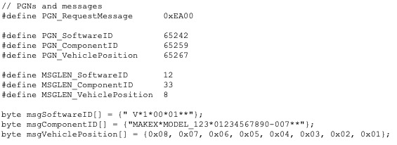
Note: The content of all messages was randomly chosen.
In the setup() routine, we need to define the various message filter, in this case only for the request message (Software ID, Component ID, and vehicle position are not received; they are responses from our J1939 application).
//
Set the message filter
j1939.SetMessageFilter(PGN_RequestMessage);
We leave all other settings such as preferred source address, address range, and NAME to their default values (see file ARD1939.h).
It is important to know that there is a specific ARD1939 feature that involves the handling of the Request message:
As defined in the SAE J1939 Standard, the Request message is 0xEA00, where the LSB is used as the destination address, i.e. the address of the ECU that is supposed to provide the requested information (e.g. 0xEA80, where 0x80 is the destination address).
The ARD1939 protocol stack’s message filter, however, will allow every message in the 0xEAxx range to pass when you set any filter PGN in the 0xEAxx range.
This behavior is necessary to allow the global address (255), meaning there are scenarios where one ECU requests the information from all nodes in the network.
As a consequence, it is mandatory that the application, in addition to the Request message, also verifies the destination address with its own address.
In the loop() function, we add the code to check for the Request message and the requested PGN as highlighted in the following:
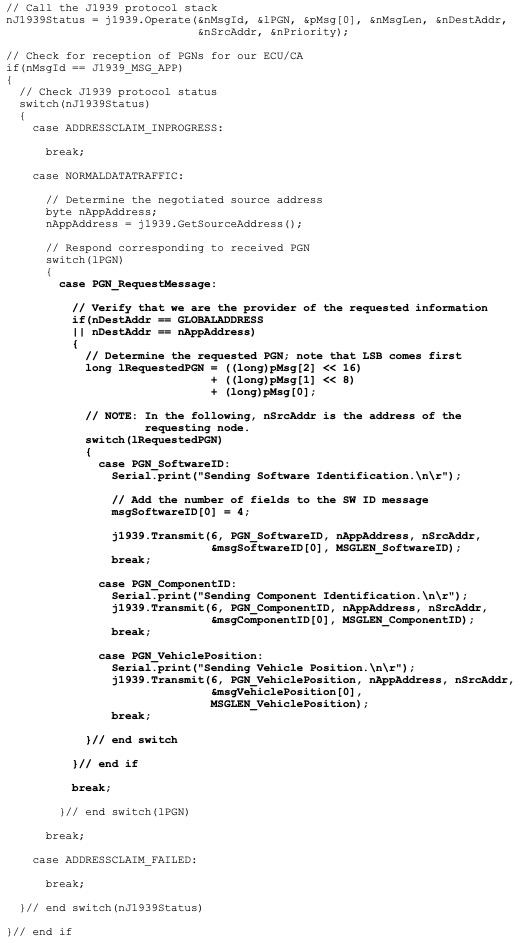
Note: The added code for this J1939 application will work on both Arduino hardware versions, the Uno and the Mega 2560.
In order to test the application, I did not use another Arduino this time but entered the data for the Request message manually into the ADFweb software tool as shown here:
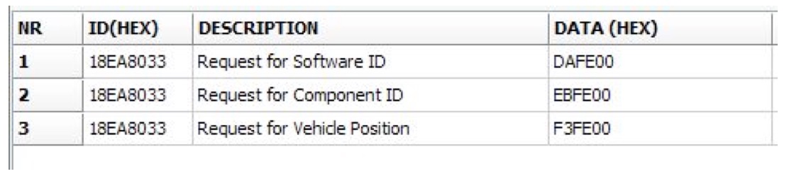
- Line 1: Node 0x33 requests the Software Identification from node 0x80.
- Line 2: Node 0x33 requests the Component Identification from node 0x80.
- Line 3: Node 0x33 requests the Vehicle Position from node 0x80.
Note: Since the Arduino is the only J1939 node in the network, it will claim address 0x80 (128). In the ADFweb software tool, I used 0x33 as the requestor’s address.
The printout on the Arduino’s serial monitor is as expected:
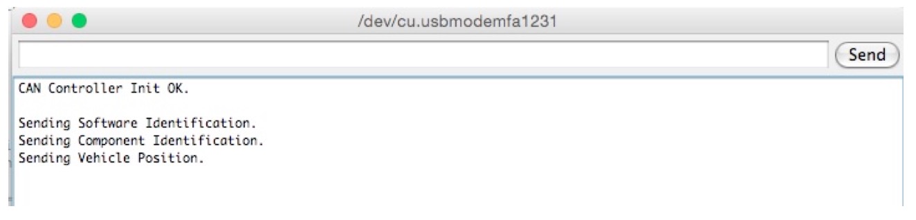
However, the J1939 data traffic as recorded on the bus came initially as a surprise, but, naturally, then it all made sense.
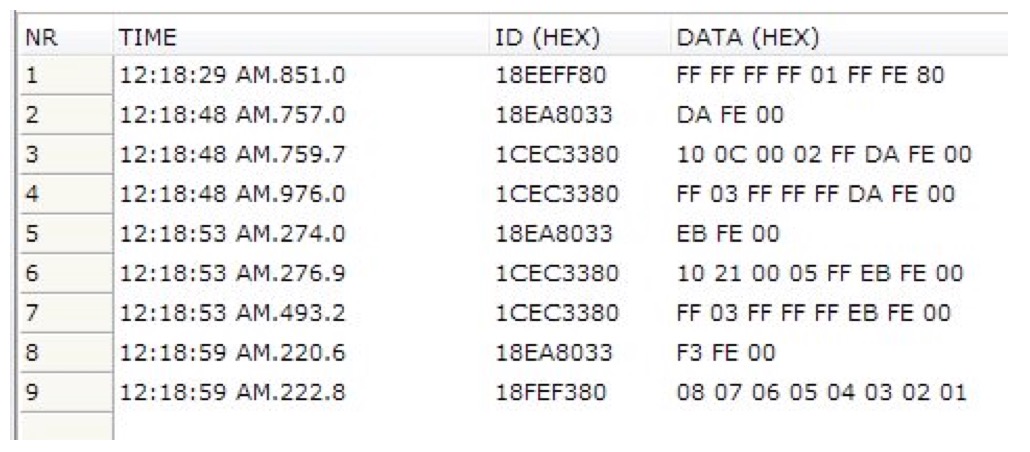
- Line 1: The Arduino claims address 0x80.
- Line 2: Request message for software identification.
- Line 3: The Arduino sends a Request to Send message.
- Line 4: The Arduino sends a Connection Abort message due to timeout.
- Line 5: Request message for component identification.
- Line 6: The Arduino sends a Request to Send message.
- Line 7: The Arduino sends a Connection Abort message due to timeout.
- Line 8: Request message for Vehicle Position.
- Line 9: The Arduino sends the Vehicle Position data.
First of all, lines 8 and 9 bare no surprise. The PGN for Vehicle Position (65267 = 0xFEF3) does not fall into the address range for peer-to-peer communication, thus the message ID contains only the senders address (0x80), i.e. that of the Arduino.
However, in the case of message requests for Software and Component Identification, the ARD1939 reports a timeout through means of the Connection Abort message. Both messages, software and component identification, are longer than eight bytes and thus require the use of the Transportation Protocol (TP), in this case an RTS/CTS session, since this is a peer-to-peer communication. The timeout is caused, because there is no J1939 node with the address 0x33 in the network (and the ADFweb tool acts only as a passive network member).
In order to establish a communication without timeout errors, we need to connect another Arduino node with a source address of 0x33, and in the setup() routine we need to set filters for all three PGNs, software identification (65242), component identification (65259), and vehicle position (65267).
Finally, the result is as expected:
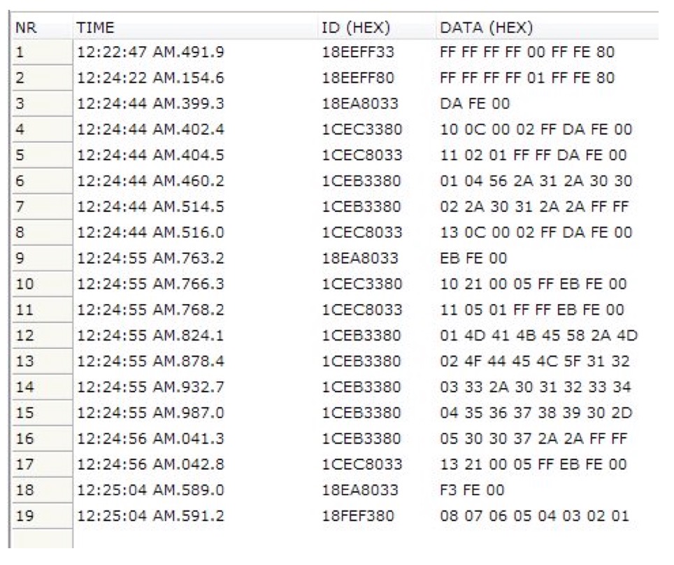
- Line 1: One Arduino claims address 0x33.
- Line 2: The other Arduino claims address 0x80.
- Line 3: Request message for software identification.
- Line 4 – 8: Software identification is transmitted and confirmed.
- Line 9: Request message for component identification.
- Line 10 – 17: Component identification is transmitted and confirmed.
- Line 18: Request message for vehicle position.
- Line 19: Vehicle position is transmitted.

SAE J1939 has become the accepted industry standard and the vehicle network technology of choice for off-highway machines in applications such as construction, material handling, and forestry machines. J1939 is a higher-layer protocol based on Controller Area Network (CAN). It provides serial data communications between microprocessor systems (also called Electronic Control Units - ECU) in any kind of heavy duty vehicles. The messages exchanged between these units can be data such as vehicle road speed, torque control message from the transmission to the engine, oil temperature, and many more.
A Comprehensible Guide to J1939 is the first work on J1939 besides the SAE J1939 standards collection. It provides profound information on the J1939 message format and network management combined with a high level of readability.