Recent Posts
ESP32 Processor: Adding a CAN Bus Transceiver
Posted by on
This post is an excerpt from our application note Controller Area Network (CAN) Development with ESP32.
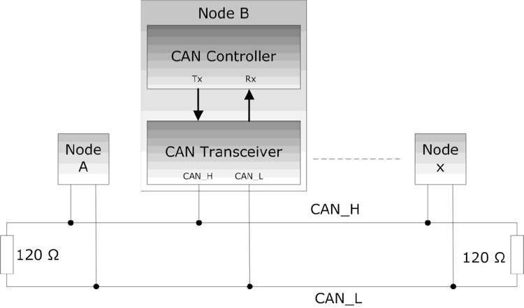
As a quick reference, I want to address the need for a CAN transceiver. As mentioned in the previous chapter, the ESP32 has an internal CAN Bus controller. However, this doesn't mean you can directly connect it to a network. You will need a line driver (transceiver) to convert the controller’s TTL signal to the actual CAN level, which is a differential voltage that the ESP32 cannot provide. The use of differential voltage significantly enhances the reliability of CAN on a hardware level.
The next image compares both signals, TTL and differential voltage:
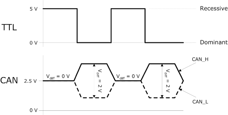
The actual signal status, recessive or dominant, is based on the differential voltage between CAN_H and CAN_L (2V during dominant bit time; 0V during recessive bit time).
As with many other ESP32 hardware features, the CAN controller output (CAN_TX, CAN_RX) can be assigned to almost any GPIO. In the following, we assume GPIO25 (CAN_TX) and GPIO26 (CAN_RX), which appear to be virtual industry standards.
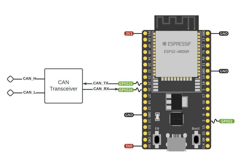
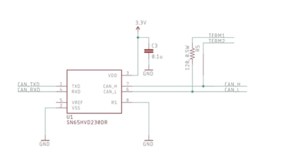
The following image shows a schematic utilizing the popular SN65HVD CAN transceiver:
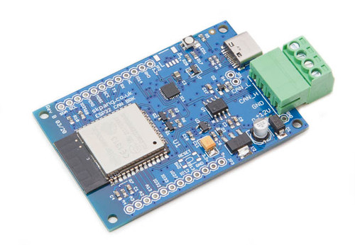
ESP32 WiFi, Bluetooth Classic, BLE, CAN Bus Module
This board has an onboard ESP32 WROOM-32 WiFi, Bluetooth Classic, BLE Module, and a CAN Bus port with a transceiver. Also onboard are an RGB LED and IO pins on a 0.1" pad.
Programming is accomplished through the popular Arduino IDE connected to the USB-to-Serial converter with a USB-C connector, automatic bootloader, and reset. The ESP32 is a low-cost, low-power system-on-chip microcontroller with integrated Wi-Fi and dual-mode Bluetooth. It employs a Tensilica Xtensa LX6 microprocessor in dual-core and single-core variations.
It includes built-in antenna switches, RF baluns, a power amplifier, a low-noise receive amplifier, filters, and power management modules. More Information...
 Loading... Please wait...

