Recent Posts
CAN FD (CAN Bus with Flexible Data Rate) Prototyping For Embedded Systems Such As Arduino, Raspberry Pi
Posted by on
CAN FD was created to accommodate increases in bandwidth requirements within automotive networks. The CAN FD protocol has brought the software closer to "real time" through the minimization of delays between instruction and transfer of data (latency) and higher bandwidth. CAN FD also allows for more storage capacity in a data frame. While the classic CAN Bus can manage up to 8 bytes of data within a frame, CAN FD can hold up to 64. The increase of data capacity is accomplished through a reduction in relative overhead and improvements to firmware simplicity and efficiency when transmitting large data objects.
CAN FD also minimizes the number of undetected errors through optimization in the performance of the CRC-algorithm. Also, CAN FD is compatible with existing CAN 2.0 networks, allowing the new protocol to function on the same network as classic CAN. CAN FD has been determined to transmit data up to 30 times faster than the classic CAN Bus.
Due to its higher communication speed, CAN FD constraints are more stringent in terms of line parasitic capacitances. Therefore, all components on the line have seen their "capacitance" budget reduced compared to the regular CAN Bus. For that reason, semiconductor suppliers have released new components approved by car makers. This approval reflects the need for interoperability between all CAN FD systems. Indeed, selected ESD protection components are compatible with all transceivers (CAN or CAN FD) and withstand ISO7637-3.
For more information on CAN FD, see:
In order to support prototyping CAN FD devices with embedded systems, Copperhill Technologies offers various breakout boards for the Arduino (and other embedded systems) and CAN FD HATs for the Raspberry Pi. The breakout boards provide different connections, such as CAN_H & CAN_L, UART and SPI. All boards come with thorough technical documentation, schematics, and programming samples.
Breakout Boards for Arduino And Other Embedded Systems
- CAN-Bus CAN FD Breakout Board 5VDC - This is a CAN-Bus breakout board with Flexible Data Rate using the Microchip MCP2561FD chip. The output pins are on both screw terminals and a DB9 connector. The DB9 can be configured for use with an OBDII cable, SAE J1939 cable, or CAN Analyser pin-out via solder bridges. More Information...
- CAN FD Breakout Board With SPI Interface - The CAN FD breakout board utilizes the Microchip MCP2517FD CAN FD controller in combination with the MCP2562FD CAN Bus transceiver. More Information...
- Isolated CAN FD Breakout Board - This is an isolated CAN Bus breakout board with Flexible Data Rate using the Analog Devices ADM3055E IC with a data rate of up to 12 Mbps. The output pins are on both screw terminals and a DB9 connector. More Information...
CAN FD HATs For Raspberry Pi
- PiCAN CAN Bus FD Board With Real-Time Clock For Raspberry Pi - The PiCAN FD board provides CAN Bus FD (Flexible Data Rate) capability for the Raspberry Pi 3. It uses the Microchip MCP2517FD CAN FD controller with MCP2562FD CAN transceiver. More Information...
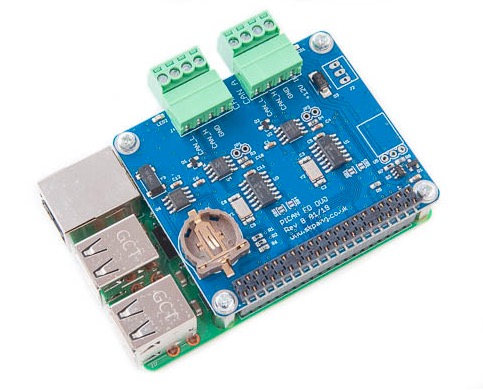
- PiCAN FD - CAN Bus FD Duo Board with Real Time Clock for Raspberry Pi - This PiCAN FD Duo board provides two-channel CAN-Bus FD capability for the Raspberry Pi. It uses the Microchip MCP2517FD CAN controller with MCP2562FD CAN transceiver. Connection are made via 4-way screw terminal. A real-time clock with battery back up (battery not included) is also on the board. More Information...
 Loading... Please wait...

