Loading... Please wait...
- Home
- Breakout Boards
- CAN FD Breakout Board With SPI Interface


)

Product Description
Free Shipping Within the United States!
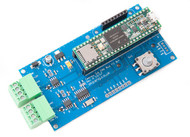
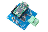
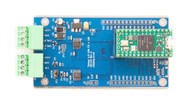
The MCP2517FD is a cost-effective and small-footprint CAN FD controller that efficiently connects to a microcontroller over an SPI interface. Consequently, the CAN FD channel presents an extension to a microcontroller that is either lacking a CAN FD peripheral, or that doesn’t have sufficient CAN FD channels.
The MCP2517FD supports both, CAN Bus data frames in the Classical format (CAN2.0 A/B) and CAN Flexible Data Rate (CAN FD) format.
Features
- Conforms to ISO11898-1:2015
- Supports both CAN 2.0B and CAN FD
- Arbitration Bit Rate up to 1 Mbps
- Data Bit Rate up to 8 Mbps
- Up to 10MHz SPI Clock Speed
- 31 FIFOs configurable as transmit or receive
- 32 Flexible Filter and Mask Objects
- One Transmit Queue
- 32-bit Time Stamp
- Bus Health Diagnostics and Error Counters
- Requires 5v supply with 3.3v or 5v logic
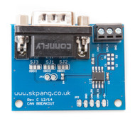
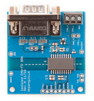
Configuring the DB9 Connector
The CAN connection is available via the DB9 connector. The connector can be configured for different pinout, either for ODB-II or standard CAN.
ODB-II Cable
Close the solder bridges on the lefthand side on SJ1, SJ2 and SJ3 as indicated below with a red dot.

Standard CAN Cable
Close the solder bridges on the righthand side on SJ1, SJ2 and SJ3 as indicated below with a green dot.

Termination Resistor
There is a 120 Ohm resistor installed on the board. To activate the terminator, solder a 2-way header pin to JP3, then insert a jumper.

Documents
 Understanding and Using Controller Area Network
Theory and Practice
This book to offers a hands-on guide to designing, analyzing and debugging a communication infrastructure based on the Controller Area Network (CAN) bus.
Although the CAN bus standard is well established and currently used in most automotive systems, as well as avionics, medical systems and other devices, its features are not fully understood by most developers, who tend to misuse the network.
This results in lost opportunities for better efficiency and performance.
- Offers the first comprehensive guide to bridging the gap between theory and implementation of the widely accepted Controller Area Network (CAN) bus;
- Provides examples and best practices for design of communication systems, as well as time and reliability analysis of communication on the CAN bus
- Improves the reader’s ability to design, analyze and debug a communication infrastructure based on the CAN bus;
- Focuses on the practical implementation of the communication stack for CAN and the implications of design choices at all levels, from the selection of the controller, to software development and architectural design.
The authors offer a comprehensive range of architectural solutions and domains of analysis. It also provides formal models and analytical results, with thorough discussion of their applicability, so that it serves as an invaluable reference for researchers and students, as well as practicing engineers.