Blog
Recent Posts
The Two Elements of the SAE J1939 Protocol Stack
Posted by on
Any SAE J1939 hardware must support SAE J1939/1x and SAE J1939/21; otherwise, they’re useless because these standards describe the CAN bus physical layer and the basic protocol features.
That part is sufficiently covered (i.e., for demonstration purposes) by our CAN shield, while the cabling and connectors may not necessarily J1939-compliant.
A fully functional SAE J1939 protocol software must support one mandatory element, SAE J1939/81 (address claim process), and, if needed, SAE J1939/21 (transport of up to 1785 bytes per message).
Note: The Transport Protocol (TP) implementation, i.e., the transport of up to 1785 data bytes in a message, is highly application-specific. Some ECUs and their control applications (CAs) will need it; some won’t.
In the following, I will cover the basics of the SAE J1939/21 Transport Protocol (TP) and the Address Claim Procedure according to SAE J1939/81.
SAE J1939/21 - Transport Protocol (TP)
Even though highly effective in passenger cars and small industrial applications, Controller Area Network (CAN) alone was not suitable to meet truck and bus communications requirements, mainly since its communication between devices is limited to only eight bytes per message. However, it is possible to extend the size of a CAN message by implementing additional software, i.e., so-called higher layer protocols. J1939 is such a higher layer protocol, and it supports up to 1785 bytes per message.
In order to support a size of more than eight bytes, the message needs to be packaged into a sequence of eight-byte size messages. Consequently, the receiver of such a multi-packet message must re-assemble the data. Such functions are defined as Transport Protocol (TP) Functions, and they are described in SAE J1939/21.
In order to package CAN messages into a sequence of up to 1785 messages (as well as to re-assemble the CAN frames into one data package), the J1939 Transport Protocol defines the following:
- Each multi-packet message is being transmitted by using a dedicated Data Transfer PGN (60160, TP.DT = Transport Protocol Data Transfer), i.e. all message packets will have the same ID.
- The flow control is managed by another dedicated PGN (60146, TP.CM = Transport Protocol Communication Management).
- The message length must always be 8 bytes (DLC = 8).
- The first byte in the data field contains a sequence number that ranges from 1 to 255.
- The remaining 7 bytes are filled with the data of the original long (> 8 bytes) message.
- All unused data bytes in the last package are being set to 0xFF.
The method of using a sequence number plus the remaining seven data bytes yields a total of (255 packages times 7 bytes/package) 1785 bytes per multi-packet message.
As it is the case with regular 8-byte CAN messages, multi-packet messages (i.e., messages longer than eight bytes) can be transmitted as a broadcast message (BAM = Broadcast Announce message) or peer-to-peer (RTS/CTS = Request to Send / Clear to Send).
Note: The SAE J1939/21 Standard requires that an ECU supports one BAM and one RTS/CTS session simultaneously.
For more information, see:
SAE J1939/81 - Address Claim Procedure
While other higher layer protocols based on Controller Area Network (CAN) do not support node address assignments per default, the SAE J1939 protocol provides yet another ingeniously designed feature to uniquely identify Electronics Control Units (ECU) and their primary function.
Note: As a reminder, a J1939 network node is usually called an “ECU.” Each ECU can maintain more than one “Control Application (CA).” Therefore, the technical requirements generally refer to a CA rather than an ECU.
The SAE J1939/81 Standard lists several technical requirements for the address claiming process:
- Each control application (CA) must be capable of providing its unique 64-bit NAME.
- CAs must successfully claim an address prior to sending messages (other than those for claiming an address) into the network.
- The inability to successfully claim an address must be handled and reported to the network.
- The CA must follow the network initialization associated with the address claiming process.
- The CA must support a minimum set of network management requirements, including required responses to power interruptions.
For more information, see:
- SAE J1939 Address Claiming Procedure Overview...
- SAE J1939 Address Management Messages (Address Claim PGNs)...
SAE J1939 Starter Kit and Network Simulator
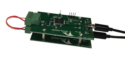
The JCOM.J1939 Starter Kit and Network Simulator are designed to allow the experienced engineer and beginner to experiment with SAE J1939 data communication without connecting to a real-world J1939 network, i.e., a diesel engine.
To establish a network, you need at least two nodes. That fact applies especially to CAN/J1939, where the CAN controller will shut down after transmitting data without receiving a response. Therefore, our jCOM.J1939 Starter Kit and Network Simulator consist of two J1939 nodes, namely our jCOM.J1939.USB, an SAE J1939 ECU Simulator Board with USB Port.
The jCOM.J1939.USB gateway board is a high-performance, low-latency vehicle network adapter for SAE J1939 applications. The board supports the full SAE J1939 protocol according to J1939/81 Network Management (Address Claiming) and J1939/21 Transport Protocol (TP).
SAE J1939 Network Management And Address Claim Procedure
The following is an excerpt from A Comprehensible Guide To J1939 by Wilfried Voss. According to SAE J1939/81, network management procedures are used to “collectively manage the network”. The chapters on network management have no logical structure (Again, explaining the function of an automobile, starting with the details of the fuel injection system); they explain the address claim messages first in [...]
Guide To SAE J1939 - Address Claiming Procedure Overview
The following is an excerpt from A Comprehensible Guide To J1939 by Wilfried Voss. While other higher layer protocols based on the CAN Bus do not support dynamic node address assignments per default, the SAE J1939 standard provides yet another ingeniously designed feature to uniquely identify ECUs and their primary function.Note: The CAN standard in itself does not support node (ECU) addresses, only [...]
SAE J1939 Programming with Arduino - Claiming Address With Contending Node
This post is part of a series about SAE J1939 ECU Programming & Vehicle Bus Simulation with Arduino. Now let’s have the two nodes compete for their addresses, since they both use the same preferred source address. For that purpose, it is important to consider which node starts up first, and the test results will demonstrate the difference.Test #1: Mega [...]
SAE J1939 Programming with Arduino - Claiming Address With No Contending Node
This post is part of a series about SAE J1939 ECU Programming & Vehicle Bus Simulation with Arduino. The first and by far simplest test is to check whether or not the node (Arduino Mega 2560) engages into the address negotiation process. This test is accomplished by a simple power cycle (reset) of the unit when no other competing node [...]
SAE J1939 Programming with Arduino - Address Claim Procedure (SAE J1939/81)
This post is part of a series about SAE J1939 ECU Programming & Vehicle Bus Simulation with Arduino. Network Management under SAE J1939 is primarily represented by the Address Claiming Process. While other higher layer protocols based on Controller Area Network (CAN Bus) do not support node address assignments per default, the SAE J1939 protocol provides yet [...]
SAE J1939 Programming with Arduino - Address Claiming Procedure
This post is part of a series about SAE J1939 ECU Programming & Vehicle Bus Simulation with Arduino. In the following, we will focus merely on two basic messages, Request Message and Address Claimed (Yet again, for further, more detailed information see the literature recommendation in the appendix).The Request Message is used by a CA to request information, such as NAME [...]
SAE J1939 Programming with Arduino - Address Claim And Preferred Address
This post is part of a series about SAE J1939 ECU Programming & Vehicle Bus Simulation with Arduino. For the purpose of a quick address claiming process, each control application should maintain a preferred address. SAE J1939/81 recommends that the preferred address (i.e. the address the ECU/CA attempts to claim on power-up) should be re-programmable to permit the proper configuration of [...]
SAE J1939 Programming with Arduino - Address Claim Technical Requirements
This post is part of a series about SAE J1939 ECU Programming & Vehicle Bus Simulation with Arduino. The SAE J1939/81 Network Management defines the processes and messages associated with managing the source addresses of applications communicating on an SAE J1939 network. Network management is concerned with the management of source addresses and the association of those [...]
SAE J1939 Programming with Arduino - SAE J1939/81 - Address Claim Procedure
This post is part of a series about SAE J1939 ECU Programming & Vehicle Bus Simulation with Arduino. Network Management under SAE J1939 is primarily represented by the Address Claiming Process. While other higher layer protocols based on Controller Area Network (CAN Bus) do not support node address assignments per default, the SAE J1939 protocol provides yet another ingeniously designed [...]
 Loading... Please wait...


