 Loading... Please wait...
Recent Posts
ESP32 Processor: Adding CAN/CAN-FD Controllers per SPI Port
Posted by on
This post is an excerpt from our application note Controller Area Network (CAN) Development with ESP32.
The internal CAN controller SJA1000 does not support CAN-FD and is not CAN-FD tolerant. To use CAN-FD with the ESP32, you need to employ CAN-FD breakout boards that are accessible per the ESP32’s SPI ports.
Note: The SPI ports are not limited to CAN-FD controllers; they also support Classical CAN controllers, such as the Microchip MCP2515. The Microchip MCP2515 is a very popular chip, and its software support is superior to that of the ESP32’s SJA 1000, thus allowing a wider range of applications.
SPI stands for Serial Peripheral Interface, a serial full-duplex and synchronous interface. The synchronous interface requires a clock signal to transfer and receive data. The clock signal is synchronized between one central control ("master") and multiple peripheral devices ("slaves"). Unlike UART communication, which is asynchronous, the clock signal controls when data will be sent and when it should be ready to read.
Only a master device can control the clock and provide a clock signal to all slave devices. Data cannot be transferred without a clock signal. Both master and slave can exchange data with each other. No address decoding is required.
The ESP32 has four SPI buses, but only two are available: HSPI and VSPI (Default). They are being selected per software, and I will explain the specifics in the SPI programming chapter.
Again, in SPI communication, there is always one controller (also known as a master) that controls other peripheral devices (also known as slaves).
While you can configure the ESP32 as either a master or a slave, we will use it as a master for all our CAN-FD applications.
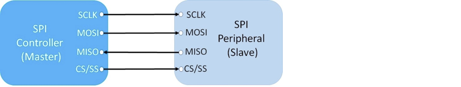
The above image shows the connection between two SPI devices that use four signals:
- SCK/SCLK Clock Signal
- MISO Master In Slave Out
- MOSI Master Out Slave In
- CS/SS Chip Select
Many ESP32 boards come with default SPI pins pre-assigned. The pin mapping for most boards is as follows:
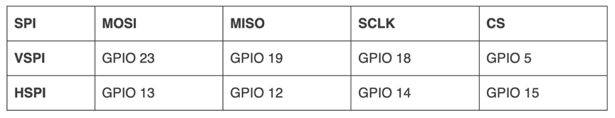
Keep in mind that the default SPI pins may vary depending on the board you are using. Therefore, it is important to check the pinout for your specific board. In some cases, certain boards do not have pre-assigned SPI pins, so you will need to set them in the code. Generally, if not specified, the board will use the VSPI pins when initiating an SPI communication with the default settings.
If you are unsure about your board’s default SPI pins, you can execute a code as described in Finding your ESP32 Board Default SPI Pins.
I would like to address the Chip Select (CS) signal in more detail because it enables the ESP32 to communicate with up to three SPI devices. This means that you can connect up to three CAN/CAN-FD controllers per SPI port (HSPI, VSPI). While the default settings are GPIO5/GPIO15 on most systems, you can assign additional CS output signals to any GPIO. The CS signal initiates access to the selected CAN controller.
Another important signal is the interrupt (INT) input signal. Each CAN controller provides an interrupt output signal when a CAN data frame is received, which triggers an Interrupt Service Routine (ISR) on the processor. This allows for the timely processing of CAN data frames. Each INT signal can be assigned to any GPIO per code.
It is possible to poll all CAN controllers without using ISRs because the ESP32 is fast enough for the task. However, interrupt-driven data processing is more reliable, especially when your application requires a lot of code.

ESP32 WiFi, Bluetooth Classic, BLE, CAN Bus Module
This board has an onboard ESP32 WROOM-32 WiFi, Bluetooth Classic, BLE Module, and a CAN Bus port with a transceiver. Also onboard are an RGB LED and IO pins on a 0.1" pad.
Programming is accomplished through the popular Arduino IDE connected to the USB-to-Serial converter with a USB-C connector, automatic bootloader, and reset. The ESP32 is a low-cost, low-power system-on-chip microcontroller with integrated Wi-Fi and dual-mode Bluetooth. It employs a Tensilica Xtensa LX6 microprocessor in dual-core and single-core variations.
It includes built-in antenna switches, RF baluns, a power amplifier, a low-noise receive amplifier, filters, and power management modules. More Information...