Blog
Recent Posts
ESP32 Development Kits with Onboard CAN Bus Controller
Posted by on
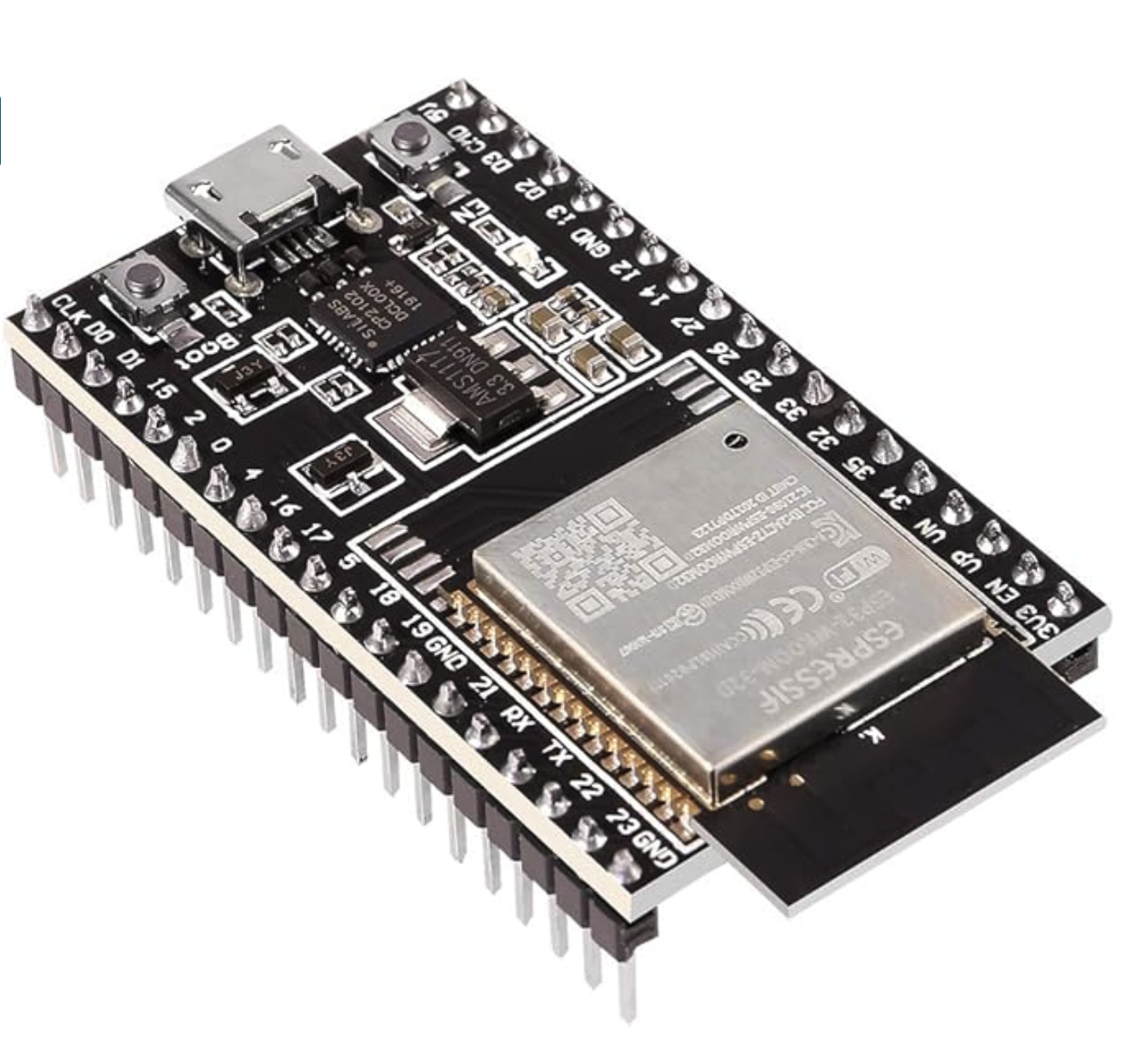
The ESP32 is a low-cost, low-power system-on-chip microcontroller with integrated WiFi and dual-mode Bluetooth. It is equipped with a Tensilica Xtensa LX6 microprocessor in dual-core and single-core versions. The microcontroller features built-in antenna switches, RF balun, power amplifiers, low-noise receive amplifiers, filters, and power management modules. It is the successor to the ESP8266 SoC.
There are multiple variants of the ESP32 and its associated development boards. However, my preferred choice is the ESP32-DevKitC V4 board due to its affordability and user-friendly interface. This board consists of the ESP-WROOM-32 as the main module and additional hardware for programming the ESP32 and conveniently connecting it to the GPIO Pins.
The ESP32 includes a CAN Bus controller compatible with the NXP SJA1000, making it compliant with the CAN 2.0B (ISO 11898, also known as Classical CAN) specification.
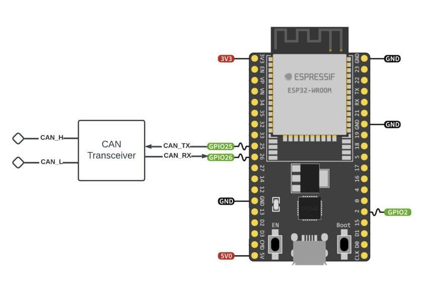
Nevertheless, as with the SJA1000, the ESP32 CAN Bus controller only provides the data link layer and the physical layer signaling sublayer. As a result, an external transceiver module is needed to convert the ESP32's CAN-RX and CAN-TX signals into CAN_H and CAN_L bus signals. The transceiver, such as the MCP2551 or SN65HVD23X, ensures compatibility with ISO 11898-2.
Consequently, when using the ESP32-DevKitC V4 board, you will require extra hardware in the form of a CAN (Classical CAN or CAN FD) breakout board. However, it is important to note that the ESP32's internal CAN controller does not support CAN-FD and is not CAN-FD tolerant. To use CAN-FD with the ESP32, you need to employ CAN-FD breakout boards that are accessible per the ESP32’s SPI ports. I will address the use of CAN FD controllers in a separate post.
The next logical step toward a CAN application with the ESP32 would be to use a breadboard, which will require wires and the assurance that the connections are solid. If this is not your preference, we offer two hardware variants.
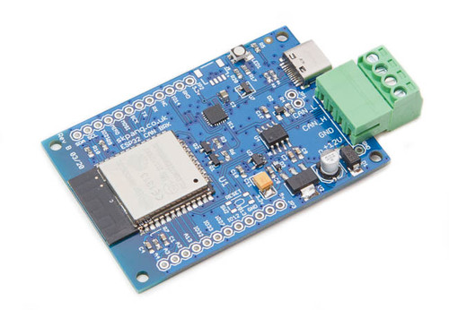
Our ESP32 WiFi, Bluetooth Classic, BLE, and CAN Bus Module comes with an onboard ESP32 WROOM-32 WiFi, Bluetooth Classic, and BLE Module and a CAN Bus port with a transceiver. Also onboard are an RGB LED and IO pins on a 0.1" pad.
Programming is accomplished through the popular Arduino IDE connected to the USB-to-Serial converter with a USB-C connector, automatic bootloader, and reset. Furthermore, we provide multiple programming examples.
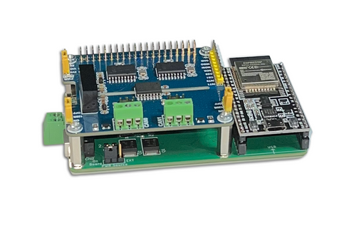
The espBerry DevBoard expands the CAN capabilities by supporting up to two CAN controllers (Classical CAN and CAN FD). It combines the ESP32-DevKitC development board with any Raspberry Pi HAT by connecting to the onboard RPi-compatible 40-pin GPIO header.
The Dual Channel CAN Bus expansion HAT, designed for the Raspberry Pi, supports the full CAN2.0 Standard. It features multiple onboard protection circuits, high anti-interference capability, and reliable operation, which makes it suitable for applications such as automotive devices or industrial automation.
The HAT is well documented, and multiple code samples use the C programming language under the Arduino IDE.
Please feel free to work through the online documentation to determine which hardware option works best for you. In addition, I am working on a detailed application note, Controller Area Network (CAN) Development with ESP32. This is a work in progress, but I already included numerous links to additional ESP32 and CAN Bus resources.
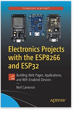 Electronics Projects with the ESP8266 and ESP32: Building Web Pages, Applications, and WiFi Enabled Devices
Copperhill Technologies highly recommends using this book for your wireless application projects. Yes, many good books and free online resources are available these days, but this is the book we are using. It made our approach to Bluetooth, BLE, and WIFI a breeze. Programming wireless applications without hassles was fun, and we will share them on this web page.
Projects throughout the book utilize the wireless functionality and processing power of the ESP microcontrollers. Projects are built in the Arduino IDE, so you don't need to download other programming software. In addition, mobile apps are now ubiquitous, making the app build projects of the book very relevant, as are the web page design projects.
In Electronics Projects with the ESP8266 and ESP32, you'll see how easy and practical it is to access information over the internet, develop web pages, build mobile apps to remotely control devices with speech recognition, or incorporate Google Maps in a GPS route tracking app.
ESP32 Processor: Adding CAN/CAN-FD Controllers per SPI Port
This post is an excerpt from our application note Controller Area Network (CAN) Development with ESP32. The internal CAN controller SJA1000 does not support CAN-FD and is not CAN-FD tolerant. To use CAN-FD with the ESP32, you need to employ CAN-FD breakout boards that are accessible per the ESP32’s SPI ports. Note: The SPI ports are not [...]
ESP32 Triple CAN Bus Application Through Adding Two MCP2515 Ports
The first question that may arise when talking about accessing the MCP2515 CAN Bus controller per ESP32 may be, "Why would you need an MCP2515 controller when the ESP32 comes with an internal CAN port?" Yes, I found this question in one of the online forums while researching this particular topic. The answer is easy: [...]
 Loading... Please wait...

