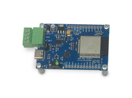
SAE J1939 Gateway And Data Logger With Real-Time Clock
Product Description
The current functionality is identical to our SAE J1939 Gateway Module With USB Port, RTC, MicroSD Memory Card, and we are adding more functions, including the recording of data without PC connection. When you buy this product, we will inform you of updates, which you can load on-site (See section Firmware Update below).
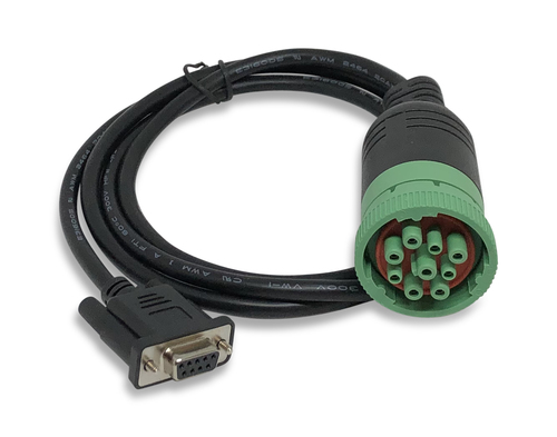 SAE J1939 9-pin Cable to DB9 Female
J1939/13 defines a standard connector for diagnostic purpose. It does allow access to the vehicle communication links. The connector is a Deutsch HD10 - 9 – 1939 (9 pins, round connector). Starting with the model year 2016 and newer trucks, commercial vehicles started showing up with the new green 9-pin plug. The main reason for the new “green” connector is that not all truck adapters and scanning tools are capable of reading 500 kbps, and it was feared that technicians would hook up older tools and cause damage to the tool, the truck, or both. The solution was to make the “Green” adapter slightly different so that it works on both the green and black adapter, thus making it backward compatible.
The cable must be ordered separately:
The SAE J1939 Gateway And Data Logger is ideal for vehicle fleet management (trucks, buses, agricultural equipment, and any other diesel engine application), prototype field testing, diagnostics, or reverse engineering.
The SAE J1939 Gateway And Data Logger records SAE J1939 message frames (PGNs) onto an onboard MicroSD memory card and timestamps them with a real-time clock (RTC). Alternatively, it can be used for mere SAE J1939 data monitoring and viewing.
In record mode, the gateway reads the data traffic without being connected to a PC. A free-of-charge Windows software is available for the device setup (PGN filtering, message-sampling frequency, etc.) as well as reviewing and re-playing the SAE J1939 data.
The data file format is Microsoft-Excel-compatible (.csv), and the data file can be retrieved directly from the SD card for further processing.
Important!
While the JCOM.XE device works as described in the user manual, it is still undergoing some firmware extensions that affect the SD card recording capabilities. At this time, the only way to retrieve the recorded data from the device is by opening the enclosure and retrieving the SD card. We are working on retrieving the data per USB connection, but we are still in the testing phase.
Difference Between CAN Bus and SAE J1939 Data Logger
Yes, you can use a regular CAN Bus Data Logger to record SAE J1939 data, and there are some fine products available in the marketplace. However, they can only record what they "see" on the bus; they are not able to send Request messages to obtain data such as VIN (Vehicle Identification Number), Engine Hours, Fuel Consumption, Vehicle Weight, Tire Pressure, Battery Potential, and further parameters necessary for fleet management.
Our SAE J1939 Data Logger comes with an integrated SAE J1939 protocol stack that allows the negotiation of a node address, which is needed to request information from the network. All setup information (message filtering and request messages) is easily set through our free-of-charge Windows software.
With these capabilities at hand, the device will start each data record file by inserting the VIN to assign the data to a specific vehicle. It will also store the detected CAN Bus baudrate.
Main Characteristics
- Easy configuration per Windows software
- Log SAE J1939 data to microSD card - microSD card not included in scope of delivery
- No PC connection needed for recording
- Date & Timestamp (with battery backup) for post analysis
- RTC battery is Lithium CR1220 - battery not included in scope of delivery
- Supports mode for mere data monitoring without recording
- Powered per SAE J1939 diagnostics connector or USB port
- Supports silent mode, PGN filters, message-sampling frequency, and more
- Supports SAE J1939 request messages (e.g. to record VIN)
- Temperature operating range: -40...+85 C
- Input Power Range of 7 VDC to 36 VDC
- Dust and splash-water proof design
Supported SAE J1939 Features Include:
- Hardware is fully SAE J1939/1x compliant
- Switchable termination resistor
- SAE J1939/21 - Data Link Layer
- SAE J1939/81 - Network Management
- Setup of Preferred Node Address
- Adjustable Node Address Negotiation Range
- Message Filters
- Full Network Communication incl. Transport Protocol
- Design Tx Messages Incl. Transmission Rate
- Configuration of Request Responses
- Configuration of Request Messages
- Network Scanner (Creates a list of all nodes in the network)
- CAN Interface
- CAN Controller integrated in microcontroller
- Fully ISO 11898-compliant
- Supports CAN 2.0A And CAN 2.0B
Recording Time
The maximum recording time depends primarily on the SD card capacity and the operation mode.
Per default, we use a 16GB SD micro card but offer options for higher capacity and/or extended temperature range.
The operating modes are:
- Diagnostics - This mode assumes the recording of selected PGNs (message filtering) for diagnostics and analysis purposes. Depending on the number of PGNs, the maximum recording time can be between 4 to 12 weeks at 8 hours/day.
- Reverse Engineering - This mode assumes the recording of the entire bus traffic. Depending on the busload, the maximum recording time will be between 5 to 15 days at 8 hours/day.
For more detailed information on this topic, see our post SAE J1939 Data Logger - SD Micro Card Capacity And Write Speed Requirements.
Material
 All materials used in this product are RoHS-compliant per EU DIRECTIVE 2011/65/EU AND AMENDMENTS.
The Restriction of Hazardous Substances Directive 2002/95/EC, (RoHS 1), short for Directive on the restriction of the use of certain hazardous substances in electrical and electronic equipment, was adopted in February 2003 by the European Union and has become a world-wide de-facto standard.
Hardware
The PCB design is based on our SAE J1939 Gateway Module With USB Port, RTC, MicroSD Memory Card. This gateway board is a high-performance, low-latency vehicle network adapter for SAE J1939 applications. It allows any host device with a USB COM port to monitor SAE J1939 data traffic and communicate with the SAE J1939 vehicle network.
The board supports the full SAE J1939 protocol according to J1939/81 Network Management (Address Claiming) and J1939/21 Transport Protocol (TP). It is also supported by an extensive programming interface for Windows and Linux/Ubuntu applications, including full C/C++/C# source code for short time-to-market developments.
The strength of the board lies in the fact that the entire SAE J1939 protocol, including all timing requirements, is stored on-chip, thus taking the burden off the main system.
The board supports a USB transfer rate of up to 480 Mbps, allowing high data throughput. Also, the onboard real-time clock supports the timestamping of the SAE J1939 data frames (PGN). Furthermore, the board comes with a MicroSD memory card slot, which opened the door to future applications such as a SAE J1939 data logger.
Enclosure
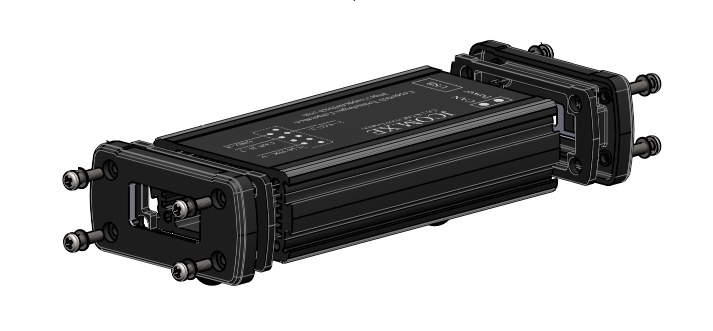
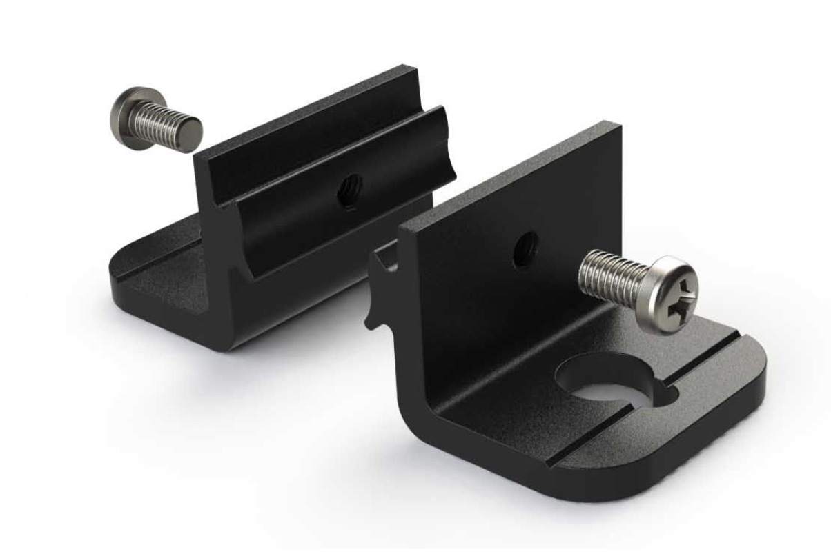
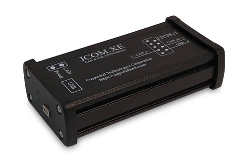
The enclosure is an off-the-shelf extruded aluminum enclosure, modified to our specs:
- Black anodized aluminum body
- Removable black powder coated cast aluminum end caps
- Grooved exterior for faster heat removal
- Enclosures include continuous gaskets and can be used indoors or outdoors (IP66)
- 5.08 x 2.70 x 1.39 in / 129.03 x 68.58 x 35.31 mm. / 0.48 lbs
- Drawing (PDF)...
USB Interface
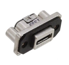 We are using the Amphenol Commercial MUSB Connectors for Harsh Environments, a family of USB connectors that provide the ideal solution for data transfer in harsh environments.
The MUSB Connectors are IP67 rated in both mated and unmated conditions.
USB 2.0 provides a maximum serial data rate of 480 Mbit/sec, which is more than sufficient for the application at hand.
The advantages of USB 2.0 over newer versions, such 3.x or USB4, are advanced resistance to vibration, dust, and moisture, as they apply in harsh environments such as offroad trucks and agricultural equipment.
CAN Bus & Power Supply
The CAN Bus and power supply connection is made via a DSUB9-M connector. In view of possible future extensions/modifications, the pinout can be modified to be compatible with SAE J1939 and OBD-II requirements as shown below.
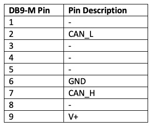
The pinout is compatible with our SAE J1939 9pin Cable to DB9 Female.
Windows Software
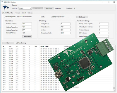
The communication protocol between the gateway and the host system (PC, Embedded System, Android System, etc.) is well documented, and we provide C/C# source code to read and write CAN data frames.
The gateway and data logger is supported by our free-of-charge jCOM1939 Monitor, an SAE J1939 Monitoring, Analyzer and ECU Simulation software under Windows.
Our JCOM1939 Monitor Software for Windows is a complete tool to monitor, analyze, record, and simulate SAE J1939 data traffic. It works in combination with our SAE J1939-USB gateways. The monitor software represents a comprehensive and easy-to-use, easy-to-understand tool that displays not only SAE J1939 data traffic; it also allows scanning the network, simulating an ECU (incl. full node address negotiation features), and responding to data request messages.
The Windows software is being extended to include the device setup (PGN filtering, message-sampling frequency, etc.) as well as reviewing and re-playing the SAE J1939 data.
Quick Trouble-Shooting Guide
Many users connect our board to their SAE J1939 network but overlook a few required steps during setup. You can prevent most initial setup problems by checking the following:
- Did you activate the termination resistors on both devices?
- Are you using the same CAN baud rate on both devices?
For further, detailed information, please refer to:
Resources
- Communication Protocol Between the Gateway and the Host System (PDF)...
- Programming the SAE J1939 ECU Simulator Board Using Visual Studio C#
- Simulating SAE J1939 PGNs Used By Truck & Bus FMS (Fleet Management System) Standard
- SAE J1939 Address Claim Procedure - SAE J1939/81 Network Management
- SAE J1939 Monitor Software - Setting Up PGN Simulation Such As Engine Coolant Temperature
- SAE J1939 To USB Gateway Records J1939 Data Frames (PGNs) To Micro SD Card
SAE J1939 Insights
- SAE J1939 Message Format And Interpretation Of PGNs...
- SAE J1939 Utilizes CAN Bus Message Collision During Bus Arbitration...
A Comprehensible Guide to J1939
SAE J1939 has become the accepted industry standard and the vehicle network technology of choice for off-highway machines in applications such as construction, material handling, and forestry machines. J1939 is a higher-layer protocol based on Controller Area Network (CAN Bus).
It provides serial data communications between microprocessor systems (also called Electronic Control Units - ECU) in any kind of heavy duty vehicles. The messages exchanged between these units can be data such as vehicle road speed, torque control message from the transmission to the engine, oil temperature, and many more.
The information in this book is based on two documents of the SAE J1939 Standards Collection: J1939/21 - Data Link Layer J1939/81 - Network Management A Comprehensible Guide to J1939 is the first work on J1939 besides the SAE J1939 standards collection.
It provides profound information on the J1939 message format and network management combined with a high level of readability.
 Loading... Please wait...

