Loading... Please wait...


)

Product Description
Free Shipping Within the United States!
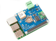
The PiCAN3 board transforms your Raspberry Pi 4 into a fully-fledged CAN‑Bus node, delivering industrial-grade performance with unmatched convenience. At its heart lies the Microchip MCP2515 CAN controller paired with the MCP2551 transceiver, enabling CAN 2.0B communication at speeds up to 1 Mb/s via a high-speed 10 MHz SPI interface. With both a DB9 connector and a 3‑way screw terminal for flexible bus wiring, it supports standard and extended data frames as well as remote frame transmissions.
One of its standout features is the onboard 3 A switch‑mode power supply (SMPS), which accepts input voltages ranging from 6 V to 20 V. This powerful regulator not only powers the PiCAN3 board itself, but also delivers clean 5 V power to your Raspberry Pi 4 and connected peripherals—making it ideal for automotive or industrial environments. The design includes reverse‑polarity protection and high-efficiency power conversion to ensure robust and reliable operation.
Time-critical applications benefit from the built-in PCF8523 real-time clock (RTC) with battery-backed timekeeping. Whether in mission-critical systems or field-deployed devices, it keeps accurate time across power interruptions, and features alarm and timer capabilities with interrupt output support for wake-up events.
The PiCAN3 complies with the HAT standard using four mounting holes and provides a 120 Ω termination resistor already in place. An interrupt pin on GPIO25 enables responsive CAN message handling. Alongside power and connectivity features, the board includes LED indicators for status monitoring, a solder bridge for DB9 configuration options, and footprints for serial LCDs or user buttons — all aimed at simplifying hardware integration.
Software setup is seamless: enable SPI in Raspberry Pi OS, install Copperhill’s SocketCAN driver, and the interface appears as can0. From there, developers can write CAN applications using either C or Python, with full support and examples provided.
Whether you're working in automotive diagnostics, robotics, industrial control, or remote data acquisition, the PiCAN3 board offers a compact, rugged, and developer-friendly CAN platform. With its comprehensive power management, accurate timekeeping, and software-ready architecture, it stands as a complete solution for building resilient, real-world CAN-enabled systems.
Key Features:
✅ Seamless CAN-Bus Integration – Powered by the Microchip MCP2515 CAN controller and MCP2551 CAN transceiver, ensuring high-performance data communication.
✅ Flexible Power Input – The onboard SMPS supports 6V to 20V DC input, providing efficient power for both the Raspberry Pi and PiCAN3, making it ideal for automotive and industrial use.
✅ Multiple Connection Options – Connect effortlessly via DB9 or the 3-way screw terminal for ultimate flexibility.
✅ Real-Time Clock (RTC) with Backup – The PCF8523 RTC offers precise timekeeping, battery backup switch-over, and alarm/timer functions for enhanced system reliability.
✅ Easy Software Integration – Install the SocketCAN driver with ease and start programming in C or Python for seamless development.
Whether you're building an automotive diagnostic tool, industrial monitoring system, or a CAN-Bus network project, the PiCAN3 with SMPS delivers robust performance and reliability.
Upgrade your Raspberry Pi with professional-grade CAN-Bus capabilities today!
Features
- CAN 2.0B at 1 Mb/s
- High speed SPI Interface (10 MHz)
- Standard and extended data and remote frames
- CAN Bus connection via standard 9-way sub-D connector or screw terminal
- Compatible with OBDII cable
- Solder bridge to set different configuration for DB9 connector.
- Onboard 120 Ohm termination resistor
- Serial LCD ready
- LED indicator
- Four fixing holes, comply with Pi Hat standard.
- SocketCAN driver, appears as can0 to application.
- Interrupt RX on GPIO25
- 5VDC@3A SMPS to power Raspberry Pi and accessories from DB9 or screw terminal
- Reverse polarity protection
- High efficiency switch mode design
- 6 VDC to 20 VDC input range
- RTC with battery backup (battery not included, requires CR1225 cell)
Documentation
Development Resources incl. Sample Code
Note: The programming samples, other than those for the RTC, are identical to those of the PICAN2:
- Python3 examples in Github...
- Example 2...
- Example 3...
- Troubleshooting your PiCAN2 CAN Interface Board for Raspberry Pi...
- PiCAN2 CAN Bus Board for Raspberry Pi - Functionality Test...
- Raspberry Pi PICAN2 Functionality Test With Two PICAN2 HATs...
- PCF8523: Real-Time Clock (RTC) and calendar...
- PCF8523: Real-Time Clock (RTC) and calendar - Data Sheet...
 Programming the Raspberry Pi - Getting Started with Python
- Set up your Raspberry Pi and explore its features
- Navigate files, folders, and menus
- Write Python programs using the IDLE editor
- Use strings, lists, functions, and dictionaries
- Work with modules, classes, and methods
- Create user-friendly games using Pygame
- Build intuitive user interfaces with Tkinter
- Attach external electronics through the GPIO port
- Add powerful Web features to your projects
Product Videos
Development of a GUI for BMW E8x Models CAN BUS interpretation. Taking CAN BUS data in via a PiCAN3 module on my raspberry pi. Then displaying that data on a web gui front end. Eventually I would like to make a CIC retrofit to my car. Still more work to be done but this is a preview. I run the PiCAN3 in loopback mode and then send CAN data into the bus which then is picked up by my python script and interpreted.
-
 BMW E8x K-CAN ...Development of a GUI for BMW E8x Models CAN BUS interpretation...