 Loading... Please wait...
Recent Posts
Testing NMEA 0183 For The PICAN-M - NMEA 0183 & NMEA 2000 HAT For Raspberry Pi
Posted by on

PICAN-M - NMEA 0183 & NMEA 2000 HAT For Raspberry Pi

Our PICAN-M (M = Marine) is a Raspberry Pi HAT with NMEA 0183 and NMEA 2000 connection. The NMEA 0183 (RS422) port is accessible via a 5-way screw terminal. The NMEA 2000 port is accessible via a Micro-C connector.
The board comes with a 3A SMPS (Switch Mode Power Supply), allowing to power the Raspberry Pi plus HAT from an onboard power source (12 VDC).
While most users engage in NMEA 2000 applications, a few need to connect older NMEA 0183 devices, and some of them had trouble connecting their hardware and receiving data through the PICAN-M. However, before I go into the details of my setup and how to test the NMEA 0183 connection, let's look at the basics to help understand the technology.
Copperhill Technologies is a member of the National Marine Electronics Association (NMEA).
A Brief Introduction To NMEA 0183
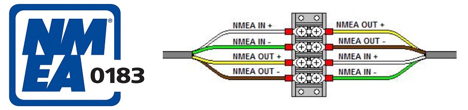
Note: The above connection diagram, copied from the NMEA.org website, shows a wrong connection, because it is not compliant with EIA-422 (RS 422). For more information see below paragraph Connecting a NME 0183 Device.
NMEA 0183 is a combined electrical and data specification for communication between marine electronics such as echo sounder, sonars, anemometer, gyrocompass, autopilot, GPS receivers and many other types of instruments. It has been defined by, and is controlled by, the National Marine Electronics Association. It replaces the earlier NMEA 0180 and NMEA 0182 standards. In leisure marine applications it is slowly being phased out in favor of the newer NMEA 2000 standard, though NMEA0183 remains the norm in commercial shipping.
The electrical standard that is used is EIA-422, although most hardware with NMEA-0183 outputs are also able to drive a single EIA-232 port. Although the standard calls for isolated inputs and outputs, there are various series of hardware that do not adhere to this requirement.
The NMEA 0183 standard uses a simple ASCII, serial communications protocol that defines how data are transmitted in a "sentence" from one "talker" to multiple "listeners" at a time. Through the use of intermediate expanders, a talker can have a unidirectional conversation with a nearly unlimited number of listeners, and using multiplexers, multiple sensors can talk to a single computer port.
At the application layer, the standard also defines the contents of each sentence (message) type, so that all listeners can parse messages accurately.
The NMEA standard is proprietary and sells for at least US$2000 (except for members of the NMEA) as of September 2020. However, much of it has been reverse-engineered from public sources.
More Resources
- NMEA 0183 (Wikipedia)...
- NMEA 0183 Interface Standard (NMEA.org)...
- Everything you need to know about NMEA 0183 (PDF)...
- NMEA 0183 Installation And Operating Guidelines (PDF)...
- The NMEA 0183 Protocol (PDF)...
A Brief Introduction To RS-422
RS-422 is a standard for serial data transfer similar to RS-232, but it uses a differential voltage, i.e., the difference between two lines (RS-232 uses a reference to ground). RS-422 uses twisted pair (difference pair) to represent the logic level. Such data transmission type represents so-called balanced transmission as it does not refer to ground, thus providing a noise-proof solution. The same noise affects both lines, which are differentiated out, allowing to carry data at considerably longer distances and higher data transfer rates. RS-422 transmits data to up to 1200 meters (~3600 feet). The maximum transfer rate is 10 Mbits/s.
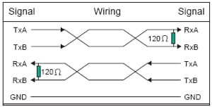
A 120 Ohm resistor acts as a terminal resistor that removes reflections during transmission over long distances. Voltage levels between twisted pair lines are 4 VDC and between transmission lines is 12 VDC. Therefore, RS-422 can be compatible with the RS-232 interface by simply connecting the negative wire of the twisted pairs to the ground.
Typically, the differential signals are referred to as RX+, RX- lines for receive and TX+,TX− lines for transmitting. However, these lines are sometimes referred to as RX-A, RX-B, and TX-A, TX-B, or as the inverted and non-inverted signals. Unfortunately, the RS-422 standard does not specify the nomenclature of the particular signals, only the signal levels. This means that each manufacturer of a device can choose their signal names and pinouts. Due to this, care must be taken when connecting two devices to ensure that the signals are matched correctly.
The Test Setup
Looking at the above wiring diagrams for NMEA 0183 and RS-422, you may notice a discrepancy between the two, specifically the wire/signal description. The confusion worsens with RS-422 devices that use A, B, Z, and Y to describe the signal. I understand that this post's topic is about NMEA 0183, and connecting NMEA 0183 devices is (or should be) straightforward. However, I approached this topic as RS-422 since the hardware on the PICAN-M port is just that. Also, I was not in the mood to buy an expensive NMEA 0183 device. So instead, I used our UART GPS Module with Real-Time Clock in combination with a RS422 to TTL Module, as shown in the following image.

Connecting a NMEA 0183 Device
As I mentioned previously, connecting an NMEA 0183 should be straightforward, but it does happen that users are misled by wrong wiring requirements. I encountered the same problem as some of my customers: The data output as displayed on the Raspberry Pi was mere garbage, but that was solved by swapping the + and - signals.
As indicated in the above NMEA 0183 wiring diagram, IN+ connects to OUT+ and IN- connects to OUT-, which is wrong, because it does not comply with the EIA-422 (RS 422) Standard. It may be that the official Standard contains the correct version, but I was not ready to spend $1000 for it.
Looking at the above RS-422 wiring diagram, TxA (+) connects to RxB (-), and TxB (-) connects to RxA (+). Regarding NMEA 0183 that results in:
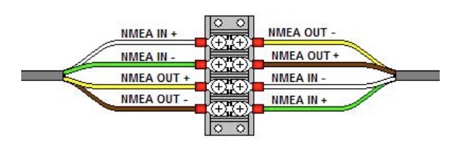
Note that I changed the polarity (+/-) on the right-hand side.
Preparing the Raspberry Pi
Before you can test the data traffic, you need to prepare the Raspberry Pi to set up the serial interface. Please, refer to the PICAN-M User Manual (pages 8 and 9) for the setup, explicitly adding the line enable_uart=1 and the raspi-config configuration.
After connecting your NEMA0183 device to the green connector of the PiCAN-M board, type the following at the command prompt:
stty -F /dev/ttyS0 raw 4800 cs8 clocal
cat /dev/ttyS0
You should now see the data traffic on the screen.
My Specific Setup
As I wrote before, I am using our GPS module with TTL signal output in combination with an RS422 module to make the GPS device RS422-compatible. However, this setup came with its own challenges, especially with the RS422 module.
First, there was the connection from the GPS device to the RS422 board that did not follow the standard connection scheme of TX-RX and RX-TX.
- GPS-RX connects to RS422-RSD (most probably a design mishap)
- GPS-TX connects to RS422-TXD
Secondly, the RS422 signals (A, B, Z, Y) follow neither the official nor the NMEA 0183 standard, and while many devices use A, B, Z, and Y, it was impossible to find a cross-reference on the Internet. Nevertheless, I figured it out:
- A = IN+
- B = IN-
- Z = OUT+
- Y = OUT-
Last, but not least, I had to use a different baudrate (9600), which I applied to the stty command. The GPS sensor can be re-programmed to 4800 baud, but for the proof of concept that was not necessary.
 Advanced Marine Electrics and Electronics Troubleshooting
Whether you are a marine electronics professional or a boat owner, Advanced Marine Electrics and Electronics Troubleshooting helps you understand the new, more powerful methods of troubleshooting marine electrical and electronic systems.
A modern boat’s sophisticated installations and networked electronics can extend the usefulness of traditional diagnostic methods based on trouble lights and multimeters.
This book will show you how to:
- Use microprocessor-based diagnostic tools and techniques from the automotive and communications sectors, adapted for boats for the first time
- Diagnose the most difficult AC and DC problems
- Protect communications and navigation electronics from interference and lightning
- Seek out and eliminate stray-current sources and galvanic corrosion