Blog
Recent Posts
Thomson Electrak HD Linear Actuator - Multiple Actuators in the Same Network Will Empty the Batteries
Posted by on

Back in April 2022, I published a post, Thomson Electrak Linear Actuator with SAE J1939 Interface for Railway and Industrial Applications intending to use the gained knowledge and publish it in form of an application report. However, after months of working with this product (time frame, not efforts), I still discovered what I call undocumented “oddities.”
These oddities caused delays during the development process. When you observe an odd behavior, the initial perception is that the software is to blame, but after hours of debugging without results, it became clear that the problems were with the actuator and its firmware.
Before I continue, I apologize to all Thomson engineers involved with this product. Please, don’t get me wrong. The Electrac HD Linear Actuator is a great product, and it is always rewarding to see the application literally move. Yet, working on this application was at times frustrating. It appears there is a demand for extended support, especially since Electrac’s user manual leaves ample room for interpretation and lacks application examples.
One of the "oddities" I found was running multiple actuators. The truth is, if you connect two or more Electrac HD actuators within the same CAN/J1939 network, you kill the sleep mode designed to minimize battery drainage. None of the actuators will ever go into sleep mode during operation.
According to the manual: “The Electrac HD utilizes a sleep mode operation when positioning is no longer required. This feature allows for a constant battery connection with minimal drain while the engine or vehicle is not running. After 5 seconds of bus inactivity, the actuator will put itself in a state of sleep.”
The actual problem is that the actuator will “wake up” with any CAN/J1939 data traffic, regardless of whether the data represents a positioning command.
Imagine the following scenario as taken from a Thomson promotional brochure explaining the advantages of CAN Bus communication:

At power-up, all actuators will wake up and transmit their initial set of data for five seconds before (theoretically) going into sleep mode when no positioning signal was received.
However, as I mentioned previously, the actuator will continue sending data when receiving any CAN/J1939 data traffic, regardless of the data representing a positioning command or not. That data traffic comes from the other actuators in the network.
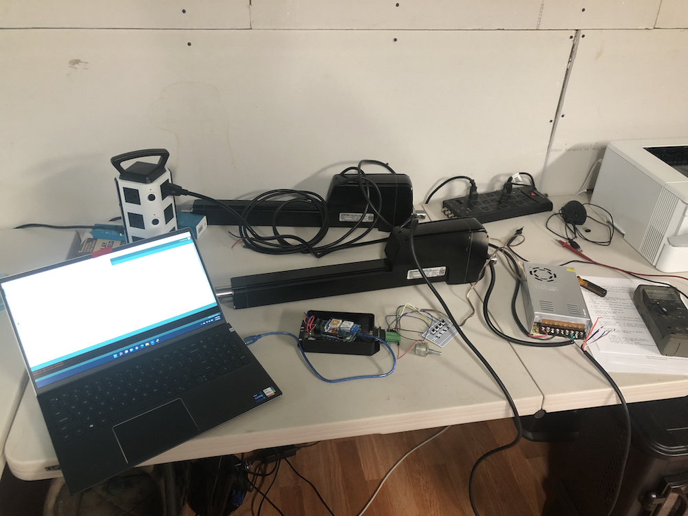
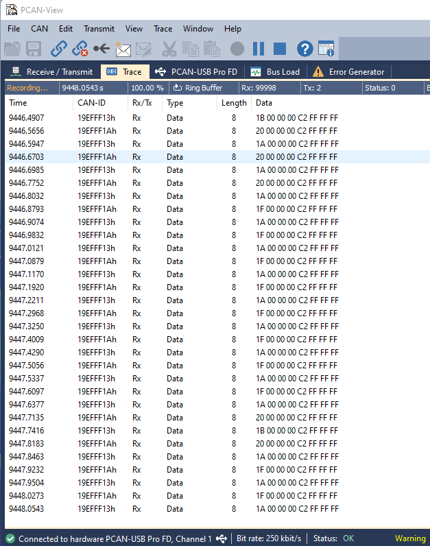
In the following example, I used two actuators with different node addresses, 0x13 and 0x1A.

They have been feeding each other with data more than 100,000 times as shown in below screen shot of the CAN/J1939 data traffic:

Naturally, they would continue into all eternity, but I didn’t have the time.
A few additional notes:
- The question arises whether the increased data traffic serves any productive purpose.
- Both actuators in this scenario report an Overload Error at startup (power-up), and they won’t move unless you clear the error, thus demanding a made-to-order program startup to address this oddity (there is no load, and the actuator is not moving).
I contacted Thomson for comment, but they ignored me.
All in all, there is no pleasing solution. If you can live with this behavior and don’t mind the increased yet unnecessary data traffic and are not using batteries to power the actuators, you are fine. Otherwise, you need to operate each actuator within its network. Furthermore, I highly recommend using galvanically isolated CAN/J1939 ports to prevent ground loops.
SAE J1939 Starter Kit and Network Simulator
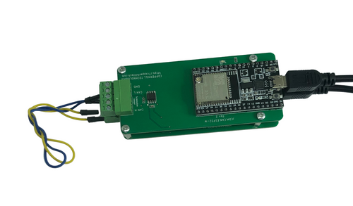
The SAE J1939 starter kit allows you to monitor, simulate, and record any PGN as defined in the SAE J1939-71 Standard but also includes diagnostic messages according to SAE J1939-73.
The starter kit was not designed to simulate specific diesel engines, but if you enter all PGNs that are being used, you can design and simulate any diesel engine.
 Loading... Please wait...

