Blog
Recent Posts
Application Note: Transmitting Analog Signals Using the SAE J1939 Protocol
Posted by on

This post is part of our series on Utilizing SAE J1939 as a Higher-Layer Protocol for Industrial Automation.
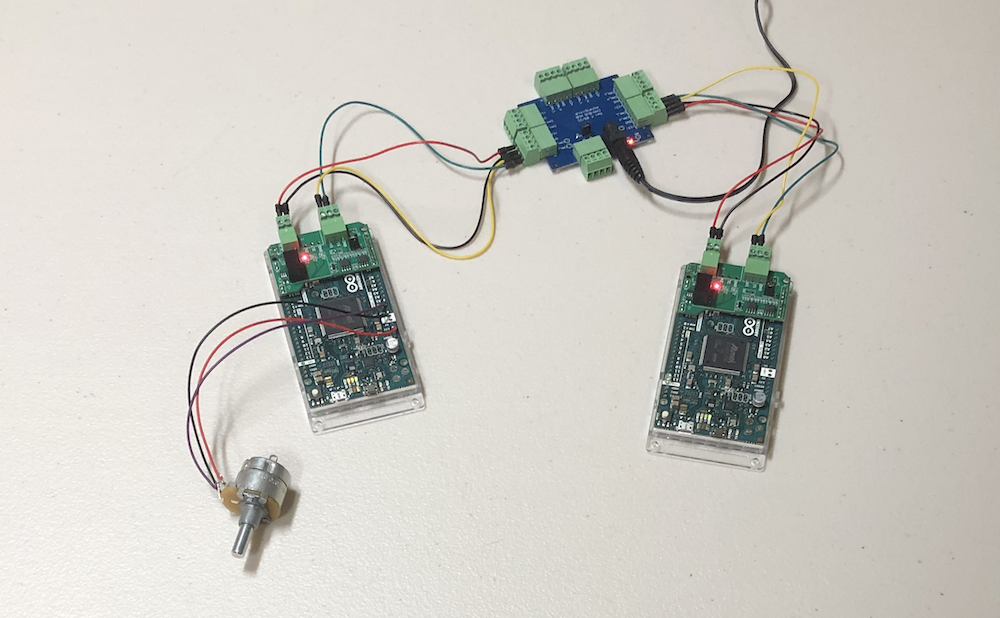
In short, the application I had in mind was to read an analog signal per one SAE J1939 node and transmit the data to another J1939 node where it controls the blinking frequency of an LED.

This project is based on an Analog Input example on the Arduino.cc website. In this example, an Arduino Uno board reads the analog input from a variable resistor, i.e., a potentiometer. The analog value determines the blink rate of an onboard LED.
It was fairly easy to replicate the application for the Arduino Due. The only difference is that the analog input supports only 3.3 VDC instead of the 5 VDC for the Arduino Uno.
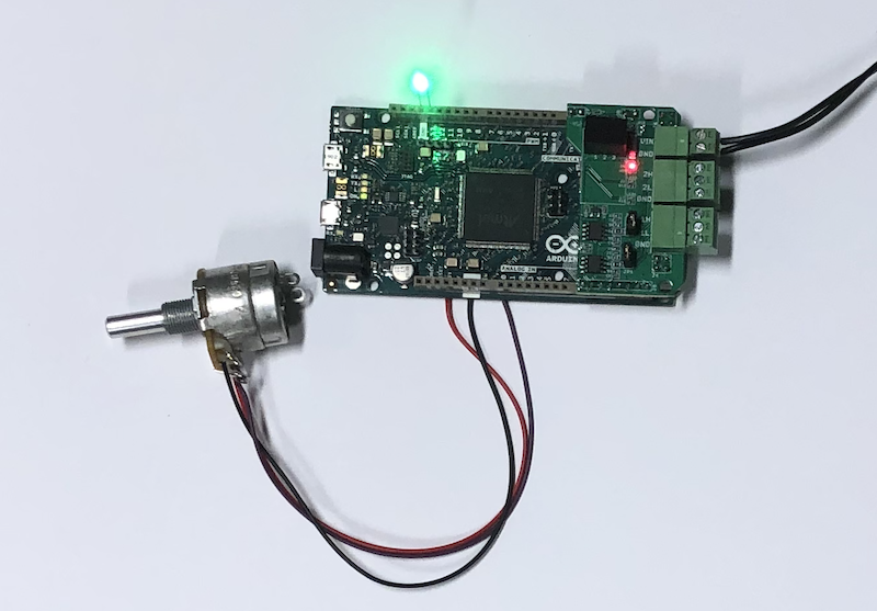
For our project, however, I am using two Arduino Due, i.e., a downsized version of our ECU Development Board With Dual CAN Bus Interface as shown in above image. These boards support only one CAN Bus port. One board reads the voltage from a connected potentiometer, the other controls a single LED.
In addition, I am using our CAN-Bus Hub with 7 Ports and DC Power Connection for the purpose of creating a neat setup but also considering adding more nodes in the future. The hub also provides the 12 VDC power for all nodes in the network.
In our next application, we will use a Raspberry Pi as a central control unit, and the hub allows for an easy hardware connection. Furthermore, we will demonstrate an easy SAE J1939 implementation for the Raspberry Pi.
ARD1939 - SAE J1939 Protocol Stack for Arduino
We at Copperhill Technologies have developed an SAE J1939 protocol stack for the Arduino line of CPU boards, which supports the Arduino Uno and Mega 2560. In addition, we have a specialized version for the Arduino Due that can be downloaded here.
I had contemplated releasing ARD1939 in the form of the original source code. Still, I ultimately decided against it, mostly out of respect for those small businesses that make a living from selling SAE J1939 devices and software tools. Instead, I provide a pre-compiled code.
The Arduino Sketch I use for the current application includes the full pre-compiled source code.
SAE J1939 ECU Programming & Vehicle Bus Simulation with the Arduino
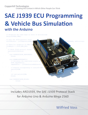
All technical information about ARD1939, the SAE J1939 protocol stack for Arduino, plus detailed description of implementation and available function calls is included in my book SAE J1939 ECU Programming & Vehicle Bus Simulation with Arduino.
Arduino sketches (software projects) include a J1939 network scanner and a simple SAE J1939 to USB Gateway application with associated Windows GUI (Visual Studio C# project). The collection of sketches is concluded by the ARD1939 project, a fully functional SAE J1939 protocol stack for the Arduino Uno and Mega 2560.
And while the book refers to the UNO and Mega 2560, the SAE J1939 protocol stack description also applies to the Arduino Due.
SAE J1939 Hardware Setup
I will not write too much about the hardware setup since it's already documented in the above-referenced Analog Input example.
The potentiometer is powered with the onboard 3.3 VDC, and the output is connected to A0. As demonstrated in the example, the LED is controlled by digital output 13. Again, contrary to the Arduino example, both components, the potentiometer and LED, are connected to their dedicated Due board.
The CAN Bus is connected as usual, i.e., CAN_L to CAN_L and CAN_H to CAN_H.
SAE J1939 Sketch
I have combined both applications, reading the analog signal and controlling the LED, into one sketch, where one #define determines the functionality:
// Define the application
#define APP_ANALOG 0
#define APP_LED 1
#define APPLICATION 1 // 0 - Reading analog signal
// 1 - Controlling LED
The Analog Read node transmits the analog data every 100 milli-seconds. The LED Control node will update the LED blink rate as soon as it receives the data from the other node.
The Analog Read node uses an ID of 128, while the LED node uses 129. Both nodes will transmit an Address Claim message at startup, but since both are using different addresses, there will be no address negotiation. For safety reasons, both nodes also have different NAMEs.
The analog data is transmitted using the proprietary PGN 65280 (0xFF00), using byte 1 (LSB) and 2 (MSB).
To repeat the point, the functionality is described in detail in the above referenced book but also at the ARD1939 download page.
However, for a quick reference, there are two important section in the sketch:
- The delay(SYSTEM_TIME); call determines the timer resolution for the protocol stack. It is currently set at one milli-second.
- The j1939.Operate call represents the actual protocol stack. The result of nJ1939Status == NORMALDATATRAFFIC indicates that the address claim process was finished successfully.
Naturally, there are more details, but I don't want to repeat what is already documented sufficiently.
Download the sketch here.
Conclusion
The application works virtually identical to the one described on the Arduino website. It demonstrates effectively that the SAE J1939 protocol can be used for industrial applications for small embedded systems. However, as I mentioned previously, for further proof, I will add more nodes while increasing busload.
Last, but not least, this project example was produced as a courtesy for those who are interested in SAE J1939 programming. In case the above example does not work in your setup, please read the following post as it solves most technical problems: A Beginner's Guide to SAE J1939 Embedded Software Development.
A Comprehensible Guide to J1939
SAE J1939 has become the accepted industry standard and the vehicle network technology of choice for off-highway machines in applications such as construction, material handling, and forestry machines. J1939 is a higher-layer protocol based on Controller Area Network (CAN Bus).
It provides serial data communications between microprocessor systems (also called Electronic Control Units - ECU) in any kind of heavy-duty vehicles. The messages exchanged between these units can be data such as vehicle road speed, torque control message from the transmission to the engine, oil temperature, and many more.
The information in this book is based on two documents of the SAE J1939 Standards Collection: J1939/21 - Data Link Layer J1939/81 - Network Management A Comprehensible Guide to J1939 is the first work on J1939 besides the SAE J1939 standards collection.
It provides profound information on the J1939 message format and network management combined with a high level of readability.
 Loading... Please wait...


