Blog
Recent Posts
SAE J1939 Programming with Arduino - Transport Protocol – RTS/CTS Session (SAE J1939/21)
Posted by on
This post is part of a series about SAE J1939 ECU Programming & Vehicle Bus Simulation with Arduino.
Test items include:
- Basic function
- Timing control
Naturally, for the RTS/CTS session we will need two SAE J1939 nodes. In my setup that means communication between the Arduino Uno and the Mega 2560 ECUs.
The test conditions are similar to the previous examples:
- The SAE J1939 protocol stack is installed on both systems.
- The Arduino Uno has a preferred address of 0x80 (128) and an ECU instance of ‘0’.
- The Arduino Mega has a preferred address of 0x80 (128) and an ECU instance of ‘1’, which means, after the address claim process, the Mega 2560 will get 0x81 (129) as its source address.
- The Arduino Mega will send the 15-byte message (as copied from the previous example) to the Arduino Uno.
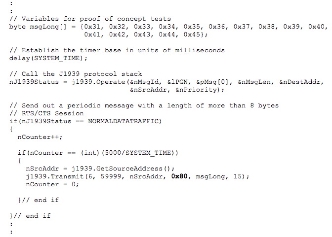
The code changes in the Mega 2560’s loop() function are minimal:

Instead of sending the message to the global address (255), we will send it to the Arduino Uno’s address of 0x80.
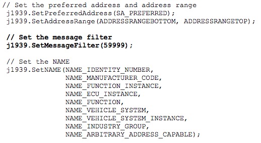
We also need to change some code in the Arduino Uno’s setup() function, i.e. we need to allow the transmitted PGN by setting the message filter. The (highlighted) code we insert looks as follows:

If we don’t set the message filter, we will see the following communication on the bus:

- Line 1: The Mega 2560 transmits the Request to Send message (source address = 0x80, destination address 0x81)
- Line 2: The Arduino Uno responds with a Connection Abort message (note the first data byte = 255) and states that it’s lacking the necessary resources (see second data byte = 0x02).
Note: The SAE J1939/21 Standard does not address all possible scenarios that may lead to a “Connection Abort” message. I deemed it necessary to provide a feedback when an RTS/CTS session cannot proceed. In this case, the reason is that the node has no use for the message.
Things get really interesting when the Arduino Uno has set the filter to allow the PGN:

Line 1:
- The
ECU at address 0x81 (129) sends a Request
to Send message to the ECU at address 0x80 (128).
- ID (HEX):
- 0x1C indicates a priority of 7.
- 0xEC80 initiates the TP (Transport Protocol), meaning this is the TP.CM (Connection Management) PGN of 0xEC00 (60416) plus the destination address of 0x80 (128).
- 0x81
(129) is the ECU’s source address
- DATA (HEX):
- 0x10 = 16 = Control byte indicating a Request to Send message
- 0x000F indicates a total length of 15 data bytes (LSB first, MSB last)
- 0x03 indicates the number of packets to be transmitted
- 0xFF (Reserved, according to SAE J1939/21)
- 0x00EA5F indicates the PGN (59999) of the multi-packet message (LSB first, MSB last)
Line 2:
- The
ECU at address 0x80 (128) sends a Clear
to Send message to the ECU at address 0x81 (129)
- ID (HEX):
- 0x1C indicates a priority of 7.
- 0xEC81 initiates the TP (Transport Protocol), meaning this is the TP.CM (Connection Management) PGN of 0xEC00 (60416) plus the destination address of 0x81 (129).
- 0x80 (128) is the ECU’s source address
- DATA (HEX):
- 0x11 = 17 = Control byte indicating a Clear to Send message
- 0x03 indicates the number of packets to be transmitted
- 0x01 indicates the next packet number
- The next two bytes are reserved (0xFF)
- 0x00EA5F indicates the PGN (59999) of the multi-packet message (LSB first, MSB last)
Line 3 through Line 5:
- Data sent by the ECU at address 0x81 (129) to the ECU at address 0x80 (128)
- The first byte indicates the sequence number, in this case going from 1 to 3
- The following 7 bytes are raw data.
- All unused data in the last package is being set to 0xFF
Line 6:
- The
ECU at address 0x80 (128) sends an End
of Message Acknowledgment message to the ECU at address 0x81 (129)
- ID (HEX):
- 0x1C indicates a priority of 7.
- 0xEC81 initiates the TP (Transport Protocol), meaning this is the TP.CM (Connection Management) PGN of 0xEC00 (60416) plus the destination address of 0x81 (129).
- 0x80 (128) is the ECU’s source address
- DATA (HEX):
- 0x13 = 19 = Control byte indicating a End of Message Acknowledgment message
- 0x000F indicates the message length (LSB first, MSB last)
- 0x03 indicates the total number of packages
- The next byte is reserved (0xFF)
- 0x00EA5F indicates the PGN (59999) of the multi-packet message (LSB first, MSB last)
SAE J1939 has become the accepted industry standard and the vehicle network technology of choice for off-highway machines in applications such as construction, material handling, and forestry machines. J1939 is a higher-layer protocol based on Controller Area Network (CAN). It provides serial data communications between microprocessor systems (also called Electronic Control Units - ECU) in any kind of heavy duty vehicles. The messages exchanged between these units can be data such as vehicle road speed, torque control message from the transmission to the engine, oil temperature, and many more.
A Comprehensible Guide to J1939 is the first work on J1939 besides the SAE J1939 standards collection. It provides profound information on the J1939 message format and network management combined with a high level of readability.
SAE J1939 Programming with Arduino - Multi-Packet Peer-to-Peer (RTS/CTS Session)
This post is part of a series about SAE J1939 ECU Programming & Vehicle Bus Simulation with Arduino. The communication of destination specific (peer-to-peer) multi-packet messages is subject to flow-control. Connection Initialization – The sender of a message transmits a Request to Send message. The receiving node responds with either a Clear [...]
 Loading... Please wait...


