Recent Posts
SAE J1939 Vehicle Bus Adapters For FMS And IoT - Test & Development Aspects
Posted by on
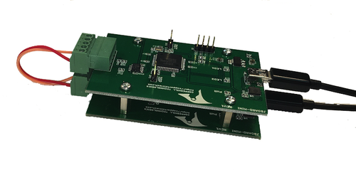
As it turns out, I recently received two inquiries that involved the testing of wireless vehicle bus adapters for FMS and IoT applications, thus requiring the simulation of SAE J1939 data traffic. In one case, the device in question was the Wireless Vehicle Adapter (WVA) by Digi; the second case involved an unspecified IoT device. In both cases, the question was whether or not our SAE J1939 ECU Simulator Board With USB Port would be suitable to (as the name actually implies) simulate SAE J1939 data traffic. And while the answer is yes, there are some other aspects that require consideration:
Are you a beginner to the SAE J1939 technology?
Nothing wrong with being a novice, but please take your time eliminating all the unknown factors during your development. A basic knowledge of the CAN Bus and SAE J1939 is essential, since it prevents problems such as CAN Bus baud rate mismatch, termination resistor issues, cabling, and other network-related topics.
For instance, it may sound very obvious to the experienced user, but you need at least two nodes to establish a network. We have had many users who worked with our SAE J1939 Simulator and who couldn't establish a connection, because they either did not connect to another J1939 node, or they worked with another J1939 device without applying the proper baud rate or misinterpreting automatic baud detection.
Does your FMS/IoT device utilize automatic baud rate detection?
Before I continue, let me point to two posts I wrote on the subject:
- SAE J1939/16 Automatic Baud Rate Detection Process...
- How CAN Bus Automatic Baudrate Detection Works And What To Consider When Connecting To A Network...
To summarize, if your SAE J1939 device offers automatic baud rate detection, it will do so by applying the "Silent Mode," making the device "invisible" to all other nodes in the network. Consequently, when using our SAE J1939 Simulator board, you still have only one node in the network, and you will run into problems.
Is your FMS/IoT device used only for data monitoring?
It is good practice that devices used for mere recording or monitoring purposes apply the "Silent Mode" (as explained above). The entire SAE J1939 protocol and its hardware requirements were designed to support highest data integrity and "Silent Mode" guarantees that the recording/monitoring device does not interfere or interact with the network. However, as explained above, that makes testing the device difficult.
The solution: The J1939 Starter Kit
If you are a beginner to the J1939 technology and/or you do not have a second J1939 node available, please consider our SAE J1939 Starter Kit and Network Simulator. The Starter Kit is a helpful tool for your development and testing by creating and analyzing SAE J1939 data traffic. Basically, it represents a two-node network to which you add your device, and while the starter kit nodes communicate with each other, your device can monitor/record the data traffic whether it uses "Silent Mode" or not.
In order to simulate some frequently used SAE J1939 signals, we have created a (configurable) simulation that transmits the following parameters (PGNs):
- Engine Speed
- Wheel Based Vehicle Speed
- Accelerator Pedal Position
- Engine Oil Pressure
- Engine Oil Temperature
- Engine Coolant Temperature
- Fuel Level
- Engine Fuel Rate
- Engine Fuel Economy
- Vehicle Position (GPS)
For more information, see our post:
One final aspect: Does your FMS/IoT device deliver sufficient data?
Many vendors in the CAN Bus industry claim SAE J1939 compatibility, because their devices support CAN 2.0 A/B, which assures support of 29-bit message identifiers as used in SAE J1939. The truth is, CAN 2.0 A/B merely addresses the hardware, specifically the CAN Bus controller functionality. In order to fully support higher-layer protocols, such as SAE J1939, you will need additional software to satisfy protocol-specific features.
For instance, the recording of the VIN under SAE J1939 reveals the most serious shortcoming of mere CAN data recording: CAN Bus data loggers can only record what they "see" on the bus; they are not able to send Request messages to obtain data such as VIN (Vehicle Identification Number), Engine Hours, Fuel Consumption, Vehicle Weight, Tire Pressure, Battery Potential, and further parameters necessary for fleet management or ELD applications.
See also our post:
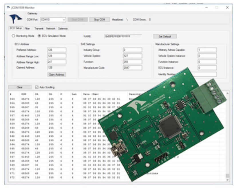
SAE J1939 ECU Simulator Board With USB Port
The jCOM.J1939.USB gateway board is a high-performance, low-latency vehicle network adapter for SAE J1939 applications. It allows any host device with a USB COM port to monitor SAE J1939 data traffic and communicate with the SAE J1939 vehicle network.
The board supports the full SAE J1939 protocol according to J1939/81 Network Management (Address Claiming) and J1939/21 Transport Protocol (TP). It is also supported by an extensive programming interface for Windows and Linux/Ubuntu applications, including full C/C++/C# source code for short time-to-market developments.
The strength of the board lies in the fact that the entire SAE J1939 protocol, including all timing requirements, is stored on-chip, thus taking the burden off the main system. The board uses a USB COM port to communicate with the main system, i.e. all data transfer is handled through a standard COM port access.
The communication protocol between the board and the main system is well documented and thus allows a porting to any computer system with a USB connection. Working source code libraries exist for Windows (C# under Visual Studio 2012/2013), Linux and its derivatives (C++ using Code::Blocks), and Raspberry Pi (C using the standard gcc compiler).
 Loading... Please wait...


