Recent Posts
SAE J1708 to UART Breakout Board - Programming SAE J1708 Network Access
Posted by on

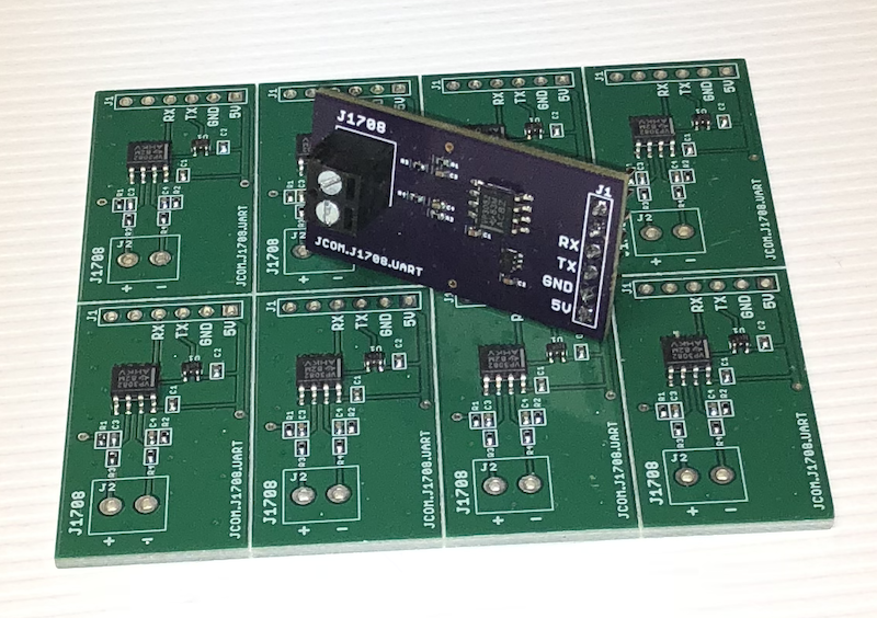
We at Copperhill Technologies have designed an SAE J1708-to-UART breakout board, and we are in the process of adding it to our e-commerce website. However, what we learned during the development is that the device is in need of some massive software support as I will explain in the following.
First of all, to go into the basics, SAE J1708 is a standard used for serial communications between ECUs on a heavy duty vehicle and also between a computer and the vehicle.
With respect to Open System Interconnection model (OSI), J1708 defines the physical layer. Common higher layer protocols that operate on top of J1708 are SAE J1587 and SAE J1922. The protocol is maintained by SAE International.
For more information, see our post A Brief Introduction to SAE J1708 and J1587.
The SAE J1708 hardware layer is based on RS485, however, with a slight modification that allows to monitor and verify the data that was transmitted (as implemented into our design). As I explained in my post Monitoring SAE J1708/J1587 Data Traffic Using The Arduino Mega2560 Or Arduino Due, the mere monitoring of SAE J708 data is fairly easy and does not require a special hardware, just a standard RS485 to UART/USB converter.
However, while this method allows monitoring J1708 data, it does not include "Idle Line Bus Synchronization," i.e. the detection of a data frame start. Unlike other standard serial protocols, SAE J1708 does not use data frame delimiters, such as a Start of Frame and End of Frame character or frame length indicator. The actual frame length depends on the number of MIDs used plus the data length used by these MIDs.
The only way to catch a data frame start is through detecting the gap between message frames or, in other words, “measuring” the idle time between message frames.
According to the SAE J1708 Standard, a receiver “may become synchronized with the bus by noting the receipt of 12 consecutive high-logic bits. …following 12 consecutive high-logic bits is the start of a message identification character MID), that is, the first character of a message.”
In other (more reality-based) words, you need to detect a time frame of 1.25 milliseconds (12 bit times per 104.17 μs - based on 9600 bauds) with no data on the network, a.k.a. idle time. The 1.25 network idle time is identical to a data frame sent with highest priority, and the assumption is that the next received character (MID) is the start of a new frame.
Things get a bit more complex when it comes to transmitting data, which involves, yet again, bus synchronization but also message collision monitoring in case that two nodes attempt bus access at the same time.
I won't get into more detail, because the bus access is described by the SAE J1708 standard. I strongly recommend acquiring a copy of the standard, in case you plan to develop your own J1708/J1587 application.

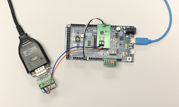
I started off with my favorite prototyping system, the Arduino Due, as shown in the image here. The J1708-to-UART board is connected to the RX3/TX3 port, and I have added some LEDs to indicate application heartbeat, bus synchronization, message collision, and data transfer.
The plan is to create an SAE J1708 starter kit based on the Arduino Due.
The software is in the making but will take some time before I can release it on this website. I checked out available resources on Github but was discouraged by the lack of documentation.
There, however, a bunch of sample projects, and they should all work with our hardware:
- C J1708 implementation for beaglebone
- UART for J1708 on Atmel AVR
- FLA J1708 drivers
- Arduino library for SAE J1708 serial communications for heavy vehicles
- python tools for j1708 messages proceed
- Python J1708 implementation for BeagleBone
- Linux serial port monitoring for J1708
- Matlab Routine to Parse J1708 Bus Data
 Loading... Please wait...
