 Loading... Please wait...
Recent Posts
Monitoring SAE J1708/J1587 Data Traffic Using The Arduino Mega2560 Or Arduino Due
Posted by on
 First of all, let me point out that this post is merely about monitoring SAE J1708/J1587 data traffic, i.e. the mere reading of data frames. SAE J1708, the hardware layer, is based on RS485, however, with a small hardware modification that allows message collision detection and prevention. In the following, I am using an RS485 breakout board that allows reading data traffic but not any data transfer into the vehicle bus. In all truth, you can write data, but please be aware that this may cause message collisions and thus unpredictable results.
Next, a short reference to SAE J1708/J1587: SAE J1708 is a standard used for serial communications between ECUs on a heavy duty vehicle and also between a computer and the vehicle.
With respect to Open System Interconnection model (OSI), J1708 defines the physical layer. Common higher layer protocols that operate on top of J1708 are SAE J1587 and SAE J1922. The protocol is maintained by SAE International.
For more information, see our post A Brief Introduction to SAE J1708 and J1587.
All you need is an Arduino Mega 2560 or Arduino Due plus RS485 interface
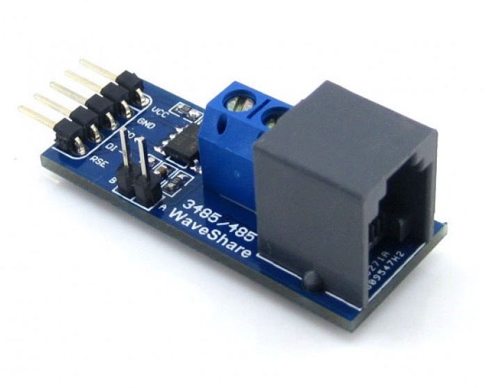
Well, neither the Mega 2560 nor the Due support RS485, the basis for the J1708 hardware layer, directly, meaning you need an RS485 breakout board. For our tests, we used our RS485 Breakout Board 5VDC.
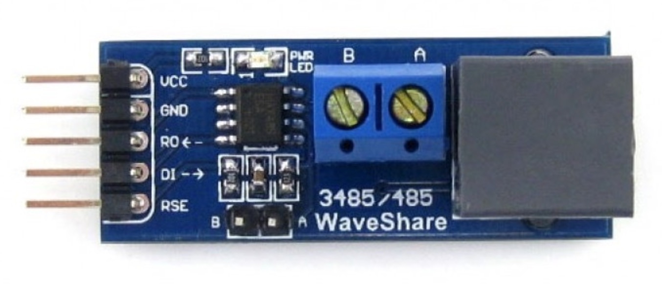
The RS485 Board features the SP485/MAX485 transceiver on board, with integrated pin headers and connectors to support multiple communication interfaces. It is designed to operate with a 5 VDC power supply.
The advantage of the Mega 2560 and Due (and the ultimate reason to choose them over the Arduino Uno) is that both boards come with three additional UART connections. Software access to these serial ports is fairly easy, since it's done in the very same way as the Arduino Serial function.
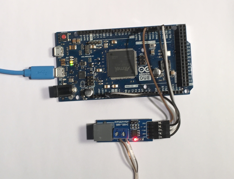
Connecting the RS485 Breakout Board
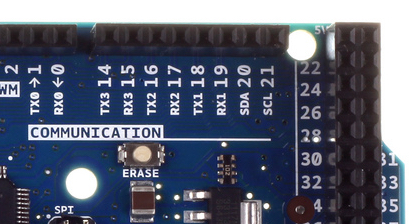
The image to the left shows the connection to the three additional serial ports (UARTs), which is identical between the Arduino Mega 2560 and Arduino Due.
The same is true for connecting the 5 VDC power to the breakout board. You can also use 3.3 VDC instead when using our RS485 Breakout Board 3.3 VDC.
See also the image below identifying the power connection on the Arduino:
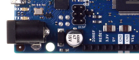
I established the connection between the Arduino Due and the RS485 Breakout Board as follows:
Arduino RS485 Board
5V ------> VCC
GND ------> GND
RX1 ------> R0
TX1 ------> DI
GPIO14 ---> RSE
Naturally, you can choose any other of the serial port connections but that must also reflect in the Arduino software (sketch).
Just a few words in regards to the RSE signal: The RSE input manages the direction of the data transfer, and this is where things get a little tricky. A high-to-low transition allows transmission of data, a low-to-high transition allows the reception of data. This method is required by the MAX485 transceiver chip.
The need for switching between read and write is based on the "half-duplex" nature of RS485, meaning you can only read or write at a time. For full-duplex mode, you would need another RS485 port, but SAE J1708/J1587 works only in half-duplex, anyways.
The RSE signal is managed per software by accessing one of the general purpose I/O signals (GPIO). In this example, I am using GPIO 14 (same pin as TX3), but, naturally, you can assign any other GPIO of your liking.
For more information on connecting the RS485 breakout board see the RS485 Board User Manual (PDF).
A First RS485 Test Sketch
In my configuration, I used a regular RS485 to USB converter and connected it to my PC. On the PC I use a terminal software (either RealTerm or Tera Term) to verify the result, which is just a simple "Hello World!" string.
setup() {
Serial1.begin(9600);
digitalWrite(14, HIGH);
}
loop() {
delay(1000);
digitalWrite(14, LOW); // Allow transmission
Serial1.print("Hello World!\n\r");
digitalWrite(14, HIGH); // Switch back to reception mode
}
The SAE J1708/J1587 Monitoring Sketch
The following Arduino sketch reads bytes from the serial port (RS485) and prints it per Serial Monitor. Admittedly, this is a very rudimentary version of displaying the data, but you get the idea.
#define RSE 14
void setup() {
Serial.begin(115200);
Serial1.begin(9600);
digitalWrite(RSE, LOW);
delay(100);
}
void loop() {
// Declarations
unsigned char sBuffer[100];
digitalWrite(RSE, HIGH);
// Check for RS485 data
int nBytes = Serial1.available();
if(nBytes > 0)
{
int nCount = Serial1.readBytes(sBuffer, nBytes);
for(int nIndex = 0; nIndex < nCount; nIndex++)
{
Serial.print(sBuffer[nIndex], HEX);
Serial.print(" ");
}// end for
} //end if
}// end loop
Please feel free to contact me through the Contact Us page on this website in case you have questions or comments.

MasterCAN V-Gate - SAE J1939 & SAE J1708 To SAE J1939 Gateway
The MasterCAN V-Gate module reads messages from an SAE J1587 and SAE J1939 network, filters and merges the data into single SAE J1939 messages, and transfers the processed data via the output CAN Bus interface. The converter is suitable for vehicles and other machinery equipped with SAE J1708 (SAE J1587) networks.
The MasterCAN V-GATE automatically and simultaneously receives SAE J1939 and SAE J1708 (SAE J1587 protocol) data. The MasterCAN device analyzes the received data, filters out a pre-configured set of most useful PGNs, generates SAE J1939 messages (PGNs), and transmits them using the CAN/SAE J1939 output interface.