- Home
- Documentation
- A Brief Introduction to SAE J1708 and J1587
A Brief Introduction to SAE J1708 and J1587
 About SAE J1708
SAE J1708 is a standard used for serial communications between ECUs on a heavy duty vehicle and also between a computer and the vehicle. With respect to Open System Interconnection model (OSI), J1708 defines the physical layer. Common higher layer protocols that operate on top of J1708 are SAE J1587 and SAE J1922. The protocol is maintained by SAE International.
The standard defines a 2-wire 18 gauge wire cable that can run up to 130 feet (40 m) and operates at 9600 bit/s. A message is composed of up to 21 characters, unless the engine is stopped and the vehicle is not moving in which case transmitters are allowed to exceed the 21 byte max message length. Messages start with a Message ID (MID) character and finish with a checksum at the end. Characters are transmitted in the common 8N1 format.
The hardware utilized are RS-485 transceivers wired for open collector operation through the use of a pullup and pulldown of the separate data lines. Transmission is accomplished by controlling the driver enable pin of the transceiver. This method allows multiple devices to share the bus without the need for a single master node. Collisions are avoided by monitoring the bus while transmitting the MID to ensure that another node has not simultaneously transmitted a MID with a higher priority.
SAE J1708, although still widely used, is replaced by SAE J1939 which is a CAN (Controller Area Network) based protocol.
Some quick facts:
- Describes the physical and data link layer according to OSI model.
- Almost always used in conjunction with the application layer protocol SAE J1587.
- Based on electronic properties from the RS-485 bus.
- Twisted pair wire with a maximum length of 40m.
- The network is based on a bus topology.
- Serial byte-oriented communication with least significant byte first.
- Transmission rate 9600 bps.
- A message contains of
- a one byte long MID (Message Identification),
- followed by a number of data bytes,
- and finally a checksum.
- A message can be up to 21 bytes long.
- Error detection and handling at collision of message transmission.
J1708 protocol uses the same transceiver as RS-485. The bus network supports at least 20 nodes with these transceivers. J1708 does not use the bus termination resistors used by RS-485.
About SAE J1587
SAE J1708 makes up the physical and data link layers while SAE J1587 makes up the transport and application layers with respect to the OSI model. SAE J1587 is used in conjunction with SAE J1708 for automobile communication.
J1587 is an automotive diagnostic protocol standard developed by the Society of Automotive Engineers (SAE) for heavy-duty and most medium-duty vehicles built after 1985. The J1587 protocol uses different diagnostic connectors. Up to 1995, individual OEMs used their own connectors. From 1996 to 2001, the 6-pin Deutsch-connector was standard. Beginning in 2001, most OEMs converted to the 9-pin Deutsch. Some OEMs still use the 6-pin Deutsch. It has mostly been used for US made vehicles, and also by Volvo. Other European brands have usually used KWP.
Some quick facts:
The J1587 protocol defines the format of J1708 messages sent between microprocessors devices in heavy duty vehicles. It also supports communication with external devices connected to the bus.
- J1587 is an application layer and is used together with J1708, which is the physical layer.
- J1587 describes a message format and defines parameters.
- A J1587 message consists of MID, PID, data bytes and a checksum.
- The length of a J1587 message is limited to 21 bytes according to J1708.
- J1587 allows for sending messages longer than 21 bytes using a connection oriented transport service (COTS).
J1708 Half-Duplex Collision Detection
SAE J1708 is basically an RS485 hardware interface without the typical 120 ohm termination resistors. In typical applications, a half-duplex RS485 transceiver chip is used to connect to the bus.
In order to avoid collisions, J1708 protocol rules dictate that the device must monitor the data bus while transmitting the first byte (MID) of its message.
The question is, how is this possible using a half-duplex transceiver? In other devices, half-duplex implied that receiving during transmission was not possible. Does the Receiver Output pin of the transceiver match the Driver Input during transmission?
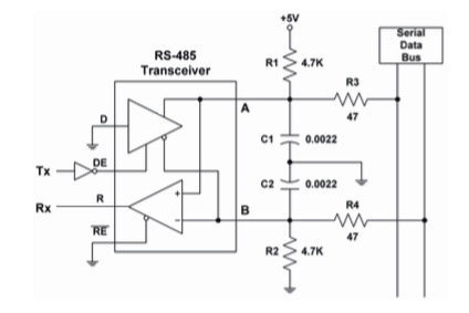
The answer to these question is that SAE J1708 uses RS-485 transceivers, but connects the serial transmit data to the enable line of the driver rather than to the data line. This means that the driver is effectively switching directions on every bit. This is similar to CANbus, in which one of the bit values is "dominant" and the other is "recessive".
The logic of each node is supposed monitor the recessive bits of the MID byte to determine whether any other node is transmitting a dominant bit at that time. If it detects this condition, the other node has a higher-priority message, and this node should immediately drop out and retry its message later.
So, connecting the UART transmit to the DE instead of the DI pin is the key as shown in the image below (picture borrowed from the SAE J1708 specs).

More Information on SAE J1708 and SAE J1587
- Introduction to SAE J1708 by Kvaser
- Introduction to SAE J1587 by Kvaser
- Texas Instrument Application Report On Automotive Physical Layer SAE J1708
A Comprehensible Guide to J1939
SAE J1939 has become the accepted industry standard and the vehicle network technology of choice for off-highway machines in applications such as construction, material handling, and forestry machines. J1939 is a higher-layer protocol based on Controller Area Network (CAN). It provides serial data communications between microprocessor systems (also called Electronic Control Units - ECU) in any kind of heavy duty vehicles. The messages exchanged between these units can be data such as vehicle road speed, torque control message from the transmission to the engine, oil temperature, and many more.
The information in this book is based on two documents of the SAE J1939 Standards Collection: J1939/21 - Data Link Layer J1939/81 - Network Management A Comprehensible Guide to J1939 is the first work on J1939 besides the SAE J1939 standards collection. It provides profound information on the J1939 message format and network management combined with a high level of readability.
=> Read More...
 Loading... Please wait...

