Recent Posts
Four Channel CAN Bus to USB Gateway Using The Arduino Due
Posted by on

In the past, I frequently received inquiries regarding the availability of a four-channel CAN Bus gateway. Such devices exist in the marketplace; however, they are usually costly, and they don't support easy customization or programming. While we at Copperhill Technologies have the ability to create such a gateway, this is primarily a matter of market potential, and we determined that the current demand did not justify the required investment of time and money. The inquiries were usually for single units, and the hardware and firmware development would need months to finish, considering that the goal would be to develop an industrial-strength device.
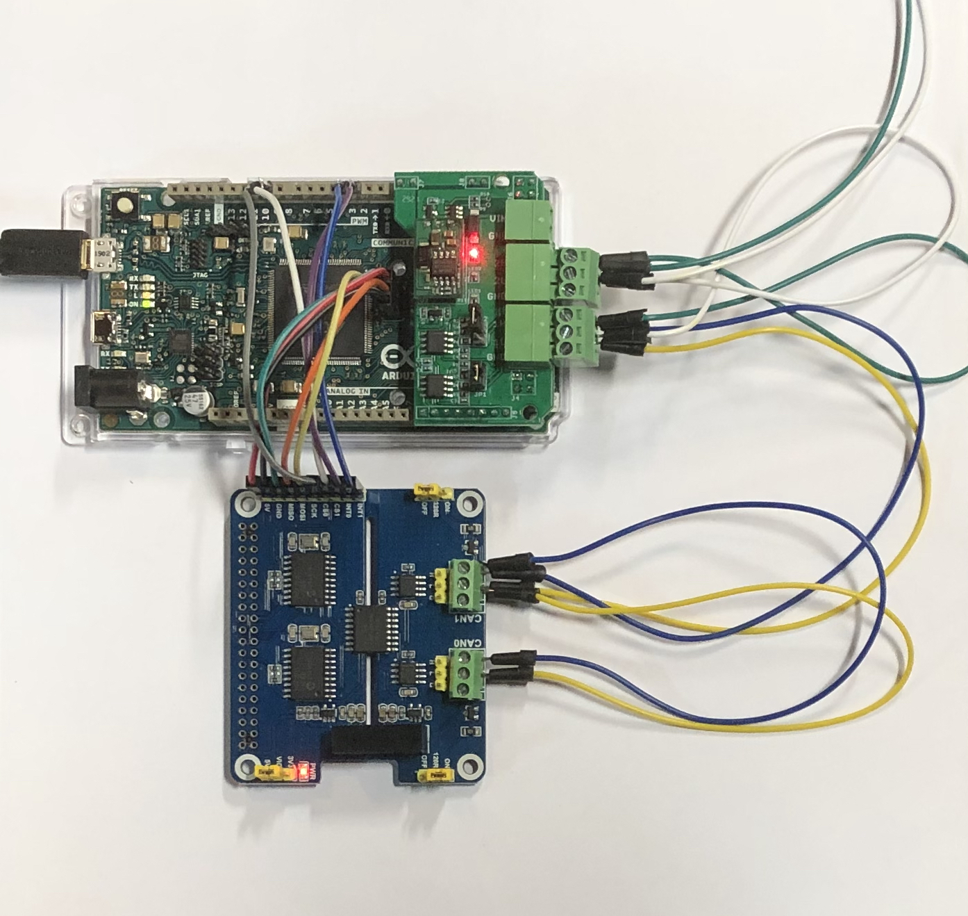
Nevertheless, we deemed creating a hardware prototype with the necessary driver software easy since we had the prototyping hardware at hand. The result we created (see above photo) is an Arduino Due with a dual CAN Bus Interface to support the on-chip CAN controller plus an external dual CAN Bus board with an SPI interface.
The Hardware
The core of the hardware configuration is our Arduino-Based ECU Development Board With Dual CAN Bus Interface, which utilizes the ARM processor's two onboard CAN controllers. The board comes with plenty of documentation and programming samples and even a free-of-charge SAE J1939 protocol stack. Please refer to the product information for more details.
The second component is our Dual Isolated CAN Bus HAT for Raspberry Pi. While the board is primarily intended for the Raspberry Pi, it also connects to any other embedded system. We chose the board because it provides two CAN Bus ports on a single board. The CAN Bus isolation is a plus but is not necessarily required. Alternatively, we could have used two of our MCP2515 CAN Bus Breakout Boards With SPI Interface because they use the same CAN Bus controller, the MCP2515. However, the dual-port board made the wiring a bit easier.
The Wiring
The connection between the Arduino Due and the external CAN Bus board contains:
- SPI Serial Interface
- Chip Select (Arduino Digital Output)
- Interrupt Signal (Arduino Digital Input)
- Power Supply (Arduino feeds 5 VDC to the CAN board)
The basic connection between the two SPI ports is as follows:
Arduino ----> CAN Board
----------------------------------------
SCK ----> SCK SPI Data Output
MISO ----> MISO SPI Clock Input
MOSI ----> MOSI SPI Data Input
SS ----> CS Chip Select
Digital Output ----> INT Interrupt Output
Since we have a dual SPI interface, we chose the following:
- CS0 = 10 - CAN0 interface using CS on digital output10
- CS1 = 9 - CAN1 interface using CS on digital output 9
- INT0 = 2 - CAN0 interrupt digital input 2
- INT1 = 3 - CAN1 interrupt digital input 3
We are preparing an application note with detailed wiring diagrams, but for the time being, please refer to:
- Dual Isolated CAN Bus HAT for Raspberry Pi...
- Arduino Due Pinout Diagram (PDF)...
- Arduino MCP2515 CAN Bus Interface Tutorial...
The CAN Bus Software Libraries
We use the following github resources:
Combining the two software libraries required some tweaking, and we will publish the sketch as soon as the previously mentioned application note is finished.
Last, but not least...
Please note that the above-presented solution does not represent a fully functional CAN Bus to USB gateway. This would require some additional programming. However, we have demonstrated the basic building blocks that will allow you to write your application.
Also, the hardware operates within a limited temperature range of 0 to 50C (32 to 122F), which is suitable for use under laboratory or office conditions but not necessarily in harsh environments such as offroad vehicles.
And yes, the above-described application can be easily extended to support CAN-FD, and we will follow up with a corresponding post on our website.
 Loading... Please wait...
