 Loading... Please wait...
Recent Posts
ESP32 Processor: CAN Bus Topology and Termination Resistors
Posted by on
This post is an excerpt from our application note Controller Area Network (CAN) Development with ESP32.
It is my experience that newcomers to the technology overlook the importance of termination resistors. Missing or misplaced resistors can lead to transmission errors or even prevent transmission altogether.
The general rule is that if you connect to an existing, fully functional network, you do not need to add any termination resistors. If you create a new network, please pay close attention to the topic as explained in the following.
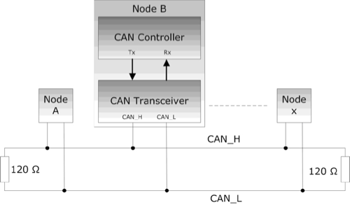
The image above demonstrates a simple CAN network. All nodes are connected by two wires, CAN_H and CAN_L. The bus line is terminated by resistors, which are typically 120 Ω and are necessary to suppress any electrical reflections on the bus.
The termination resistors should always be connected at both ends of the bus; they should never be physically attached to a CAN node because removing this specific node would cause the bus to lose proper termination.
Note: The CAN standard allows for any bus topology, but a simple, straightforward architecture is advantageous for increased reliability. However, depending on the physical bus structure, it may be difficult to determine “both ends of the bus” and may require some trial and error.
According to ISO 11898-2, the termination resistor should be between 100…130 Ω, but typically 120 Ω, with a minimum power dissipation of 220 mW. Deviations from the nominal value of 120 Ω are possible, depending on the bus topology and the baud rate. As a rule of thumb, the lower the termination resistor, the fewer possible nodes in the network.
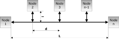
The wiring topology of a CAN network should be as straight as possible, using short cable lengths and avoiding complex network structures, even though almost any network structure is possible under CAN.
The maximum bus length (L) depends on the baud rate used. The table below displays some network topology parameters at the maximum baud rate of 1 Mbit/sec.
| Parameter | Maximum Length [ft] / [m] |
| L - Bus Length | 120 / 40 |
| l - Cable Stub Length | 1 / 0.3 |
| d - Node Distance | 120 /40 |
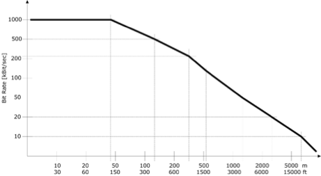
The bus length can be significantly extended at lower baud rates. The following image demonstrates the relationship between CAN baud rate and maximum physical network length.

ESP32 WiFi, Bluetooth Classic, BLE, CAN Bus Module
This board has an ESP32 WROOM-32 WiFi, Bluetooth Classic, BLE Module, and a CAN Bus port with a transceiver onboard. It also has an RGB LED and IO pins on a 0.1" pad.
Programming is accomplished through the popular Arduino IDE connected to the USB-to-Serial converter with a USB-C connector, automatic bootloader, and reset. The ESP32 is a low-cost, low-power system-on-chip microcontroller with integrated Wi-Fi and dual-mode Bluetooth. It employs a Tensilica Xtensa LX6 microprocessor in dual-core and single-core variations.
It includes built-in antenna switches, RF baluns, a power amplifier, a low-noise receive amplifier, filters, and power management modules. More Information...