 Loading... Please wait...
Blog
Recent Posts
Controller Area Network (CAN Bus) Tutorial - Extended CAN Protocol
Posted by on
The following is an excerpt from A Comprehensible Controller Area Network by Wilfried Voss.

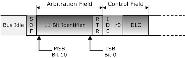
The standard CAN message frame uses an 11-bit message identifier (CAN 2.0A), which is sufficient for use in regular automobiles and industrial applications but not necessarily for off-road vehicles.
The Society of Automotive Engineers (SAE) Truck and Bus Control and Communications Subcommittee developed a family of standards concerning the design and use of devices that transmit electronic signals and control information among vehicle components. As a result, the higher-layer protocol SAE J1939, based on CAN, was born, which required some backward-compatible functionality with older RS-232-based communication protocols (SAE J1708/J1587).
The CAN standard needed to be enhanced to support a 29-bit message identifier to serve these demands. The ISO 11898 amendment for an extended frame format (CAN 2.0B) was introduced in 1995.
The 29-bit message identifier consists of the standard 11-bit base identifier and an 18-bit identifier extension. The distinction between CAN base frame format and CAN extended frame format is accomplished by using the IDE bit inside the Control Field (See picture 4.6.2). A low (dominant) IDE bit indicates an 11-bit message identifier; a high (recessive) IDE bit indicates a 29-bit identifier.
An 11-bit identifier (standard format) allows a total of 211 (= 2048) different messages. A 29-bit identifier (extended format) allows a total of 229 (= 536+ million) messages.
Both formats, standard (11-bit message ID) and Extended (29-bit message ID), may co-exist on the same CAN bus. During bus arbitration, the standard 11-bit message ID frame will always have higher priority than the extended 29-bit message ID frame with an identical 11-bit base identifier and gain bus access.
The Extended Format has some trade-offs: The bus latency time is longer (minimum 20 bit-times), messages in extended format require more bandwidth (about 20 %), and the error detection performance is reduced (because the chosen polynomial for the 15-bit CRC is optimized for frame length up to 112 bits).
The picture below shows the Control Field of a CAN data or remote frame according to the original CAN standard 2.0A:

Both bits, r1 and r0, were reserved for future use and were kept at a low (dominant) level.
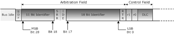
The Control Field was “re-designed” (CAN 2.0B) as shown in the picture below in order to support co-existence of 11-bit and 29-bit message identifiers on the same CAN bus network.

A low (dominant) IDE bit indicates an 11-bit message identifier, a high (recessive) IDE bit indicates a 29-bit identifier.
- Standard Format: 11 Bit message identifier
A low (dominant) IDE bit indicates an 11-bit message identifier.
- Extended Format: 29 Bit message identifier
A high (recessive) IDE bit indicates a 29-bit identifier.
The IDE (Identifier Extension) bit belongs to:
- The Control Field of the Standard Format
- The Arbitration Field of the Extended Format
The 29-bit message identifier consists of the standard 11-bit base identifier and an 18-bit identifier extension. Between the SOF (Start of Frame) bit and the end of the 11 bit (base) message identifier, both frame formats, Standard and Extended, are identical.
Following the 11-bit base identifier, the Extended Format uses an (always recessive) SRR (Substitute Remote Request) bit, which, as its name implies, replaces the regular RTR (Remote Transmission Request). The following IDE (Identifier Extension) bit is also kept at a recessive level.
With the use of a recessive SRR plus a recessive IDE bit, it is guaranteed that standard message frames (11-bit identifier) will always have higher priority than extended message frames (29-bit identifier) with an identical 11-bit base identifier (see also Chapter 6 - Bus Arbitration).
The Control Field of an extended message frame, following the 18-bit extended identifier plus RTR bit, has the format of the original CAN 2.0A standard.
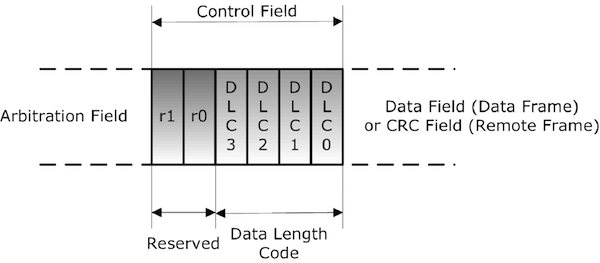
Bits r1 and r0 are reserved for future use and are always kept at a dominant level.

PiCAN 2 - CAN Bus Interface for Raspberry Pi
This PiCAN2 board provides Controller Area Network (CAN) Bus capabilities for the Raspberry Pi. It uses the Microchip MCP2515 CAN controller with MCP2551 CAN transceiver. Connection are made via DB9 or 3-way screw terminal.
There is an easy-to-install SocketCAN driver, and programming can be accomplished in C or Python.
The PiCAN board is fully compatible with the new Raspberry Pi 4 Model B.
SAE J1939 Programming with Arduino - The SAE J1939 Higher-Layer Protocol
This post is part of a series about SAE J1939 ECU Programming & Vehicle Bus Simulation with Arduino. Even though extremely effective in automobiles and small, embedded applications, CAN Bus alone is not suitable for projects that require a minimum of network management and messages with more than eight data bytes.As a consequence, higher layer protocols (additional software on [...]