 Loading... Please wait...
Blog
Recent Posts
Controller Area Network (CAN Bus) Tutorial - Dominant And Recessive Bus Level
Posted by on
The following is an excerpt from A Comprehensible Controller Area Network by Wilfried Voss.

Before discussing each bit in a CAN Bus frame, it is helpful to briefly examine the physical layer (for more details, refer to Chapter 9—Physical Layer) to understand the nature of, for instance, the SOF (Start of Frame) bit, the RTR (Remote Transmission Request) bit, and, in a later chapter, the bus arbitration.
As its name implies, the SOF bit signals the beginning of a message frame. The RTR bit separates the data from the remote frame. Understanding the dominant and recessive level on the CAN bus makes it easier to differentiate between data and remote frames.
The dominant level (TTL = 0V) always overrides a recessive level (TTL = 5V), which is essential, especially during bus arbitration.
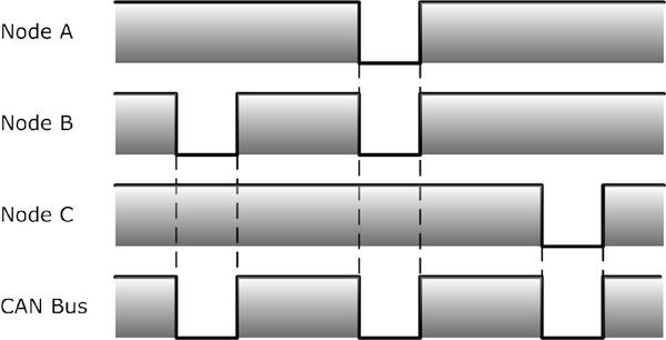
As demonstrated in the picture below, the CAN bus level will be dominant if any number of nodes in the network output a dominant level. The CAN bus level will only be recessive when all nodes in the network output a recessive level.
The physical CAN bus uses a differential voltage between two wires, CAN_H and CAN_L. A CAN controller with its TTL output uses an additional line driver (transceiver) to provide the standard CAN level (see Chapter 9 - Physical Layer). The following chapters on the CAN frame architecture and bus arbitration refer to the TTL output of the CAN controller. [1]
An equivalent from some electronics basics will explain the relationship between node output and the resulting bus level as shown in the following picture.
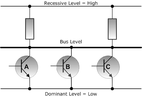
This example uses three nodes in a CAN network, represented by three transistors in an open-collector (“Wired And”) configuration. The bus level will be low (dominant) if any number of transistors in the network output a dominant level. It will only be high (recessive) when all transistors in the network output a recessive level.
| Node | |||
| A | B | C | Bus |
| 0 | 0 | 0 | 0 |
| 0 | 0 | 1 | 0 |
| 0 | 1 | 0 | 0 |
| 0 | 1 | 1 | 0 |
| 1 | 0 | 0 | 0 |
| 1 | 0 | 1 | 0 |
| 1 | 1 | 0 | 0 |
| 1 | 1 | 1 | 1 |
The following picture demonstrates the transition from an idle CAN bus to an SOF (Start of Frame), meaning the initiation of a new message transfer. It shows the output signal of a CAN node in comparison with the actual bus level.
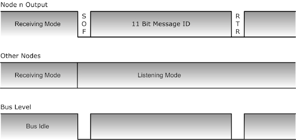
While the bus is idle, i.e., no node attempts a transmission, the bus will remain on the recessive level.
When one or more nodes attempt to start a transmission, they will output the SOF (Start of Frame) bit to the bus. An active SOF bit is per definition at the dominant level; therefore, an active SOF bit will set the bus to the dominant level.
The bus arbitration mechanism will decide which nodes requesting bus access will succeed (refer to Chapter 6 - Bus Arbitration).
The example, as shown in the picture, demonstrates the transmission of a data frame, which is indicated by a dominant RTR (Remote Transmission Request). A recessive RTR bit would indicate the presence of a remote frame, a frame requesting data from another node.
In theory, the data frame in picture 4.1.3 could be the response to a remote frame. The remote and requested data frames use the same message identifier (see also Chapter 4.4 - Remote Frame). The RTR bit, like the message ID, is part of the arbitration field.
A dominant RTR (Remote Transmission Request) bit, indicating a Data Frame, will override a recessive RTR bit (indicating a Remote Frame). As a result, in case that a Remote and Data Frame with the same message ID try to access the bus, the Data Frame will have higher priority than the Remote Frame requesting the data.
[1] Most works on Controller Area Network fail to mention this little, but significant fact before they refer to CAN frames, which may lead to the incorrect perception that CAN_L is the dominant level and CAN_H is the recessive bus level.

PiCAN 2 - CAN Bus Interface for Raspberry Pi
This PiCAN2 board provides Controller Area Network (CAN) Bus capabilities for the Raspberry Pi. It uses the Microchip MCP2515 CAN controller with MCP2551 CAN transceiver. Connection is made via DB9 or 3-way screw terminal.
There is an easy-to-install SocketCAN driver, and programming can be accomplished in C or Python.
The PiCAN board is fully compatible with the new Raspberry Pi 4 Model B.