Blog
Recent Posts
Automotive Power Management IC with LIN and CAN-FD Interfaces
Posted by on
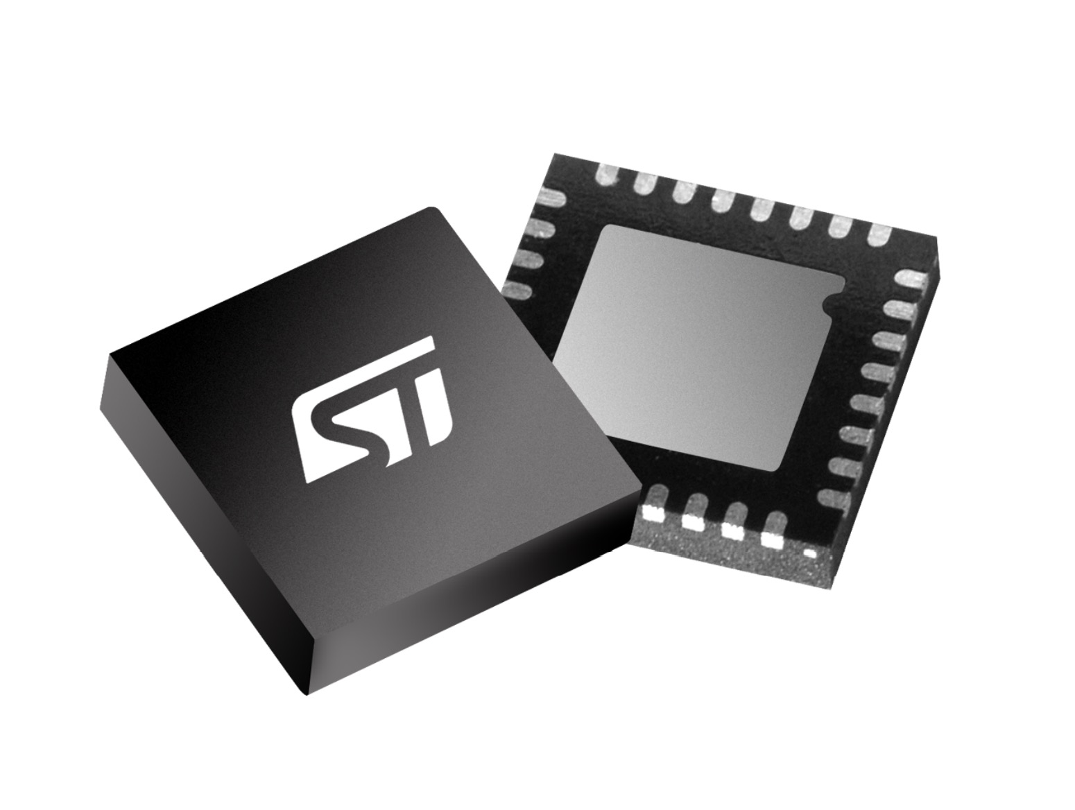
The SPSB081 by STMicroelectronics is a power management chip providing electronic control units (ECU) with power management functionality. It supports CAN FD and, optionally, comes with LIN transceivers.
The SPSB081 operates at various standby modes with programmable local and remote wake-up capabilities to minimize power consumption. The chip has a low-drop voltage regulator to supply the host microcontroller and one voltage tracker to supply external peripheral loads such as sensors. The V1 voltage regulator is available with a fixed rail (5 VDC or 3.3 VDC), overvoltage detection, and protection solution. In contrast, the V2 voltage regulator is a tracker voltage regulator of V1, programmable by SPI (Serial Peripheral Interface) with 5 VDC or 3.3 VDC). The SPI port permits control and diagnosis of the chip. Moreover, the component features four high-side drivers to supply LEDs and sensors.
The integrated CAN-FD transceiver complies with ISO 11898-2:2016 and SAE J2284 requirements. It provides local failure and bus failure diagnosis functionality. The chip also features a programmable periodic system wake-up. In TRX normal mode, the full functionality of the CAN-FD transceiver (transmitter and receiver) is available, and automatic voltage biasing is enabled. State transitions from TRX normal mode to VBAT standby mode and V1_Standby mode are possible, with no interrupt generated in this mode.
In the CAN TRX STBY mode, the transmitter is disabled, and the RxD_C pin is at the high (recessive) level. The receiver of the CAN FD transceiver can detect a wake-up pattern (WUP). In V1_standby mode and VBAT_standby mode, a WUP is forwarded to the microcontroller by an interrupt signal. There is no automatic state transition into TRX normal mode in case of a detected WUP. The microcontroller can trigger a state transition to TRX regular operation in active mode.
Furthermore, two additional sub-modes are possible (“Bias ON” or “Bias OFF”), depending on the CAN_AUTO_BIAS bit (compliant with ISO 11898-2:2016) or timeout conditions. When entering CAN TRX STBY mode, the transition is always “Bias ON.”
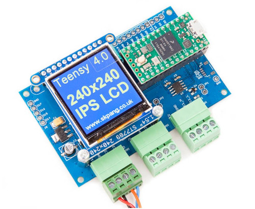
Teensy 4.0 Triple Board with Two CAN 2.0B And One CAN FD Port With 240x240 IPS LCD And MicroSD
The Teensy 4.0 Triple CAN Bus Board with 240x240 IPS LCD And MicroSD is a Teensy 4.0 board with triple CAN Bus connections, two Classical CAN 2.0B, and one CAN FD. It can be powered by an external +12 VDC power supply with reverse voltage protection. Also included is a 240x240 wide-angle IPS TFT LCD display with microSD holder.
The Teensy 4.0 is an Arduino-compatible board with an Arm Cortex-M7 microcontroller running at 600 MHz. The board is compatible with the Arduino IDE and the Arduino library. In most cases, code written for another Arduino board works with a minimum of changes on a Teensy. As the name implies, the board is tiny. For example, the current form factor is only about 18 by 36 millimeters. However, do not let the size mislead you; these boards pack a ton of functionality. For example, the new Teensy 4.0 features a megabyte of RAM, two megabytes of Flash, a bevy of I/O options, cryptographic support, a hardware floating-point processor (FPU), and a built-in real-time clock (RTC).
 Loading... Please wait...


