Blog
Recent Posts
Controller Area Network (CAN Bus) - Physical Layer And Bus Topology
Posted by on
The following is an excerpt from A Comprehensible Controller Area Network by Wilfried Voss.
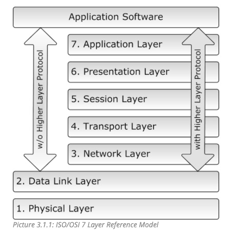
The ISO/OSI Reference Model specifies seven levels starting with the physical connection up to the actual user application, i.e., the Application Layer.
The standard CAN Bus implementation neglects the connection between the Data Link Layer and the Application Layer to save on relevant memory resources by reducing the overhead and, as a result, increasing performance as required for embedded solutions with restricted resources.
After all, all layers above the Data Link Layer require supplementary software resources (higher layer protocols).
The CAN Bus Data Link Layer is, to a certain degree, documented in the Bosch CAN Specification Version 2.0 and the ISO 11898-1 Standard.
Documentation of the CAN Physical Layer is available through two documents:
- ISO 11898-2 concentrates mainly on the physical signals on the CAN bus.
- CiA Draft Standard DS-102 recommends hardware connections and baud rates.
The following sections are designed to provide an overview of the CAN Bus Physical Layer, however, in the sense of being a “comprehensible guide”. For complete details on the exact CAN Bus signals, please refer to the data sheets of the respective CAN Bus Transceivers.
In all consequence, a description of the physical CAN layer must also include topics such as Bit Coding, Bit Timing and Synchronization, Phase Error and Resynchronization, etc. which was already detailed in Chapter 7 - Data Transfer Synchronization. These topics relate, however, to internal CAN Bus controller functions, while the following chapters describe “external” topics.
Bus Topology
The following image illustrates a sample CAN Bus network. All nodes are connected utilizing only two wires, CAN_H and CAN_L. The bus line is terminated by resistors, which are typically 120 Ohm and are necessary to suppress any electrical reflections on the bus. The termination resistors should always be connected at both ends of the bus; they should never be physically attached to a CAN node because the bus would lose proper termination in case this specific node is removed.
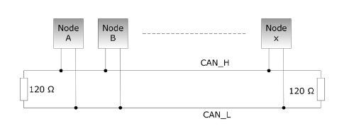
Note: CAN_L and CAN_H represent the physical connection between CAN nodes; they do not represent actual voltage levels. CAN_H will be at (nominal) 3.5 V during a dominant bit, while CAN_L will be at 1.5 V, which makes CAN_H the higher voltage. This may be the reason the creators of the CAN standard chose to use this terminology.
According to ISO 11898-2 the termination resistor should be in the range of 100…130 Ohm, but should typically be at 120 Ohm, with a minimum power dissipation of 220 mW. Variations from the nominal value of 120 Ohm are tolerable, depending on the present bus topology and the baud rate. As a rule of thumb, the lower the termination resistor, the lower is the number of nodes that can be maintained in the network.
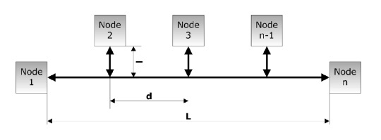
The wiring topology of a CAN Bus network should be as straight as possible, i.e., using short cable lengths and avoiding complicated network structures (even though almost any network structure is allowed).
As described in more detail in Chapter 9.6 - Maximum Bus Length, the maximum bus length L depends on the used baud rate. Table 9.1.1 shows some network topology parameters at the maximum baud rate of 1 MBit/sec.

The bus length can be extended significantly at lower baud rates (see also Chapter 9.6 - Maximum Bus Length ).
Dual CAN Bus Interface For Arduino Due With Extended Power Range
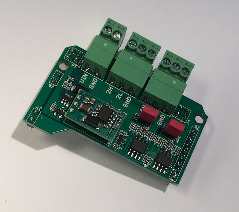
The jCOM.CAN.DUE-X, a dual CAN bus interface for the Arduino Due, is not an Arduino shield in the common sense.
The board incorporates dual CAN transceivers required by the two integrated CAN ports on the Arduino Due while allowing the operation with any Arduino-compatible shield that supports the necessary 3.3 VDC power requirements.
By combining our dual CAN port interface, the Arduino DUE microcontroller, an OBD2 or SAE J1939 cable, and open-source software libraries you are ready to go with powerful a turn-key Arduino-based dual CAN bus solution.
Leverage the 32-bit processing capability of the Arduino DUE plus the built-in CAN ports for your next prototype.
In order to more efficiently serve automotive and industrial applications, the jCOM.CAN.DUE-X board supports an extended input power range of 7 to 36 VDC to power the entire system, i.e. including the Arduino Due itself.
 Loading... Please wait...

