 Loading... Please wait...
Blog
Recent Posts
Controller Area Network (CAN Bus) - Bit Timing And Synchronization
Posted by on
The following is an excerpt from A Comprehensible Controller Area Network by Wilfried Voss.

As was explained in Chapter 7.1 - Bit Coding the CAN standard uses the Non-Return-to-Zero (NRZ) bit coding, which provides a maximum of data transport capacity, but in turn lacks sufficient means of bit synchronization between sender and receivers in a CAN network.
Bit Stuffing, i.e. the insertion of an additional bit of reversed polarity after a series of bits of the same polarity, provides a higher number of signal edges for synchronization, but, with maximum reliability requirements in mind, Bit Stuffing alone was deemed not quite sufficient.
In order to assure that all receivers in a CAN network read the transmitted frames correctly they are also required to continuously resynchronize the internal time base with the received bit stream.
This is accomplished by continuously adjusting the bit sample point during each bit time. The purpose of bit timing synchronization is to coordinate the oscillator frequencies in a CAN network and as a result provide a system wide specified time reference.
Bit Sample Point
One topic that had not been addressed so far is: When exactly does a receiving CAN node read the bit information?
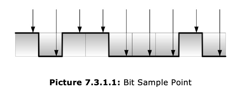
As shown in a random example in picture 7.3.1.1 the bit sample point is located somewhat close to the end of the actual bit time in order to compensate for signal propagation delays in the CAN network plus delays within the actual CAN receiver/transmitter circuits.
Since the CAN standard manages the bus access through bit-wise arbitration, it must be assured that the signal propagation time from sender to receiver and back to the sender must be completed within one bit time.
Note: CAN nodes transmitting a message to the bus also monitor the bus and compare the transmitted level bit by bit with the corresponding level on the bus. Consequently, considering the signal propagation time from sender to receiver and back to the sender is mandatory for bit monitoring.
The determination of the bit sample point, and consequently its positioning, requires an internal detection and simulation of the actual bit time reference.
Bit Time
In order to determine the exact bit sample point the CAN standard partitions the nominal bit time into four non-overlapping time segments as shown in picture 7.3.2.1.
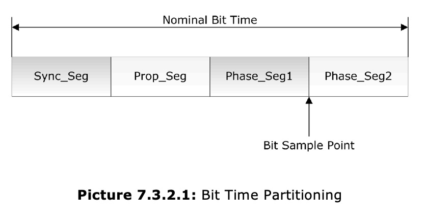
The Nominal Bit Time is derived from the Nominal Baud Rate as shown in equation 7.3.2.1:

The four non-overlapping time segments used for the partition are:
- Sync_Seg: Synchronization Segment
This segment is used to synchronize the nodes in a CAN network. A signal edge is expected within this segment. Any deviations, either a premature or delayed signal edge, will be measured and the phase buffer lengths will be adjusted accordingly, which in turn moves the bit sample point (resynchronization).
- Prop_Seg: Propagation Time Segment
This segment is used to compensate for the physical delay times within the network, such as signal propagation delay and delays within the actual CAN nodes, namely the receiver/transmitter circuits. The segment’s length must be twice these delay times to compensate for delays from sender to receiver and back to the sender (See also picture 7.3.2.3).
- Phase_Seg1/2: Phase Buffer Segment 1/2
These segments are used to compensate for signal edge phase errors. Their length may be adjusted by resynchronization. Phase_Seg1 may be lengthened while Phase_Seg2 is shortened. The length of Phase_Seg2 is programmed to the maximum length of Phase_Seg1 plus the information processing time.
The Resynchronization Jump Width defines the upper limit of the amount that is used to lengthen or shorten the phase buffers.
The Information Processing Time starts with the bit sample point and is reserved for calculation of the subsequent bit level, for instance, after a bus arbitration loss.
The Bit Sample Point is the point in time at which the bus level is read and interpreted as the value of that respective bit. Since the sample point is always at the end of Phase_Seg1, lengthening/shortening the phase buffers will move the actual sample point.
The Internal Delay Time of a CAN node is the sum of all asynchronous delays occurring during the transmission and along the reception path, caused by the bit timing logic units of the CAN controller.
Dual CAN Bus Interface For Arduino Due With Extended Power Range

The jCOM.CAN.DUE-X, a dual CAN bus interface for the Arduino Due, is not an Arduino shield in the common sense.
The board incorporates dual CAN transceivers required by the two integrated CAN ports on the Arduino Due while allowing the operation with any Arduino-compatible shield that supports the necessary 3.3 VDC power requirements.
By combining our dual CAN port interface, the Arduino DUE microcontroller, an OBD2 or SAE J1939 cable, and open-source software libraries you are ready to go with powerful a turn-key Arduino-based dual CAN bus solution.
Leverage the 32-bit processing capability of the Arduino DUE plus the built-in CAN ports for your next prototype.
In order to more efficiently serve automotive and industrial applications, the jCOM.CAN.DUE-X board supports an extended input power range of 7 to 36 VDC to power the entire system, i.e. including the Arduino Due itself.