 Loading... Please wait...
Recent Posts
SAE J1939 Programming with Arduino - J1939 Data Traffic Simulation
Posted by on
This post is part of a series about SAE J1939 ECU Programming & Vehicle Bus Simulation with Arduino.

In a previous project (see chapter SAE J1939 Simulation Example) I demonstrated the simulation of SAE J1939 data traffic.
However, the messages in that example were transmitted within a certain frequency. In the following, we will transmit messages according to user input.
As before, we will use the previous sketch and add code without removing the previously added functionality.
But, since we will transmit data according to user input, we need to separate the network scanner from the data transmission (Remember: the network scan was initiated by any user input).
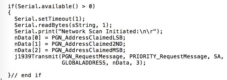
From the previous chapter’s sketch, I removed (actually, I commented out) the following code:
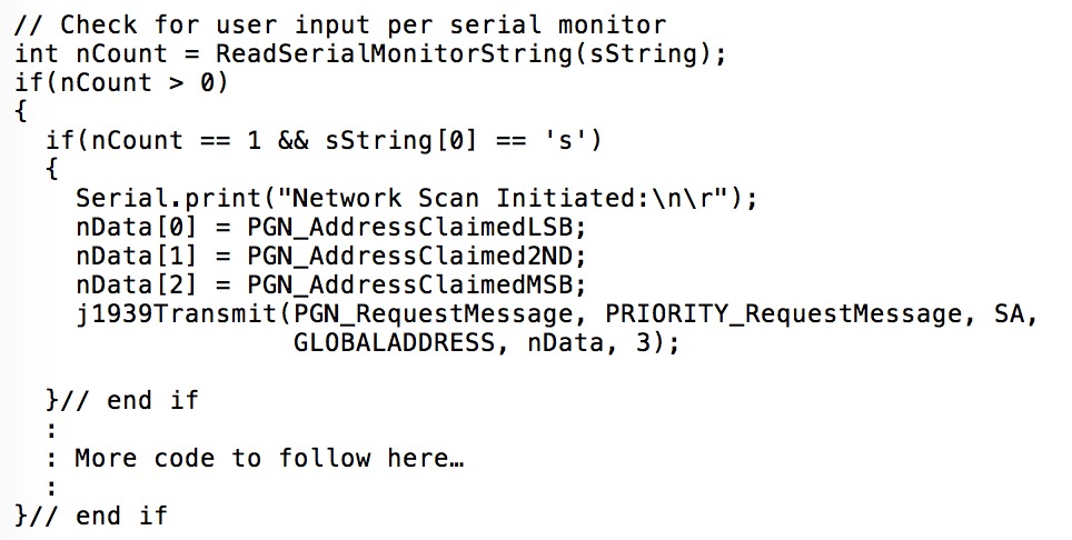
The new sketch now contains a function call ReadSerialMonitorString that returns the text string the user entered plus the length of the entry. For the network scan I chose “s” as the command. Consequently, the code looks like:
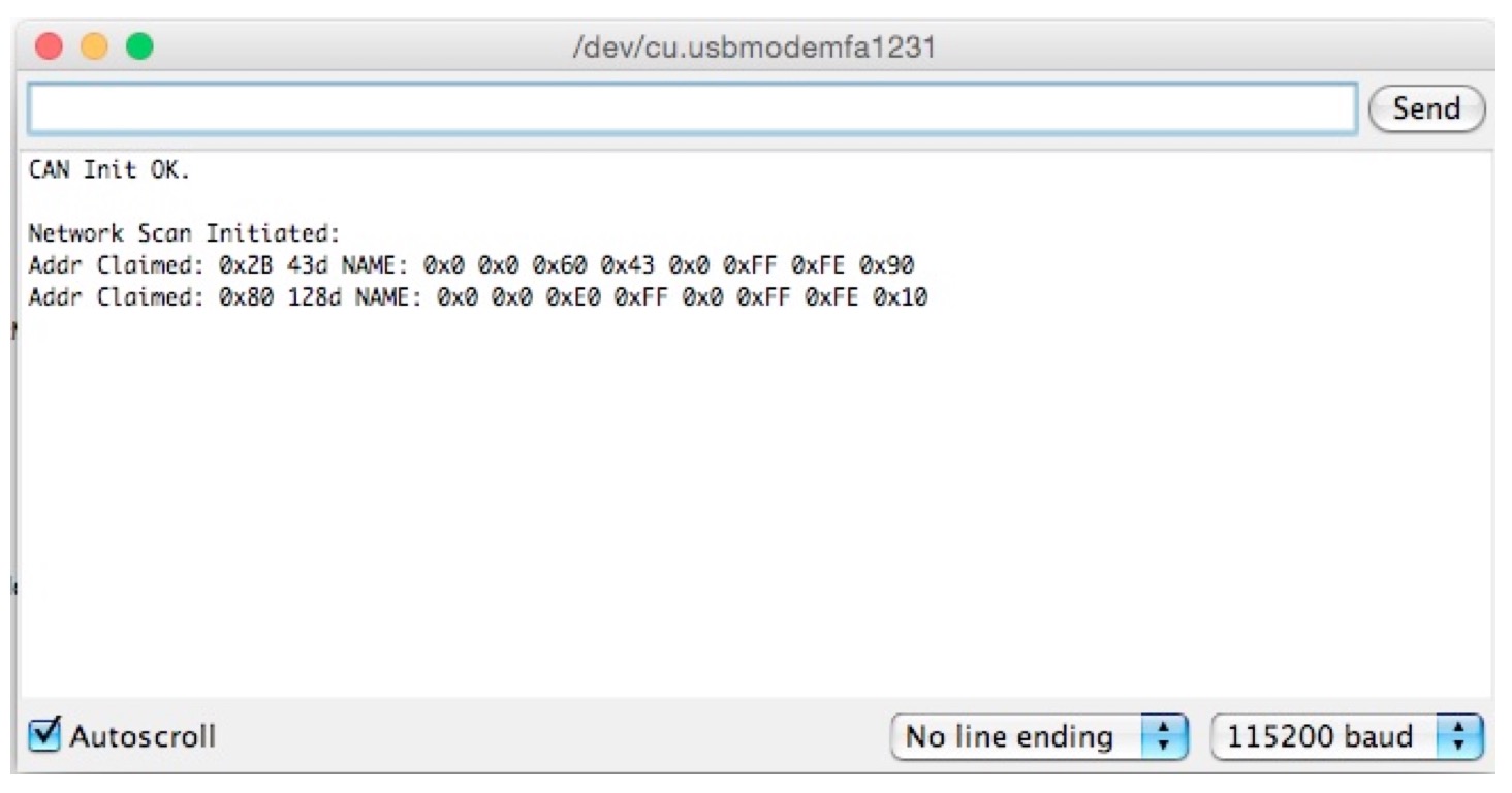
The following screen shot shows the same result as in chapter J1939 Network Scanner, but, for the sake of adding some more information, I have added the code to print the control application’s NAME.
As I mentioned previously, in order to accomplish basic gateway functionality with the Arduino, we will need to establish a communications protocol between the Arduino’s USB interface and the PC. The foundation of this USB protocol is already established through the Serial.print function and the protocol will be based on transmitting ASCII text.
In addition, we need to specify the commands to send out J1939 data according to user input. As described before, we use the letter “s” to initiate a network scan.
For the sending of a full SAE J1939 data frame, I have defined the following user input format based on text (ASCII) input:
- PGN – 4 characters
- Priority – 1 character
- Source Address – 2 characters
- Destination Address – 2 characters
- Data – 2 to 16 characters (representing 1 up to 8 data bytes)
All parameters will be separated by a space character, and the assumption is that all parameters are entered in hex format.
Example: EAFF 6 33 FF 00EE00
Per the previous example (Request for Address Claimed message), we are sending PGN 0xEAFF with a priority of 6, a source address of 0x33, the global destination address (255), and three data bytes.
Note: The following code accomplishes only a very rudimentary user input verification. Please feel free to refine the code or add more functionality to the protocol. Additional features could be, for instance, the adding/deleting of PGN filters (allowing only user-defined PGNs).
The code as shown is an extension to the previous code excerpt:
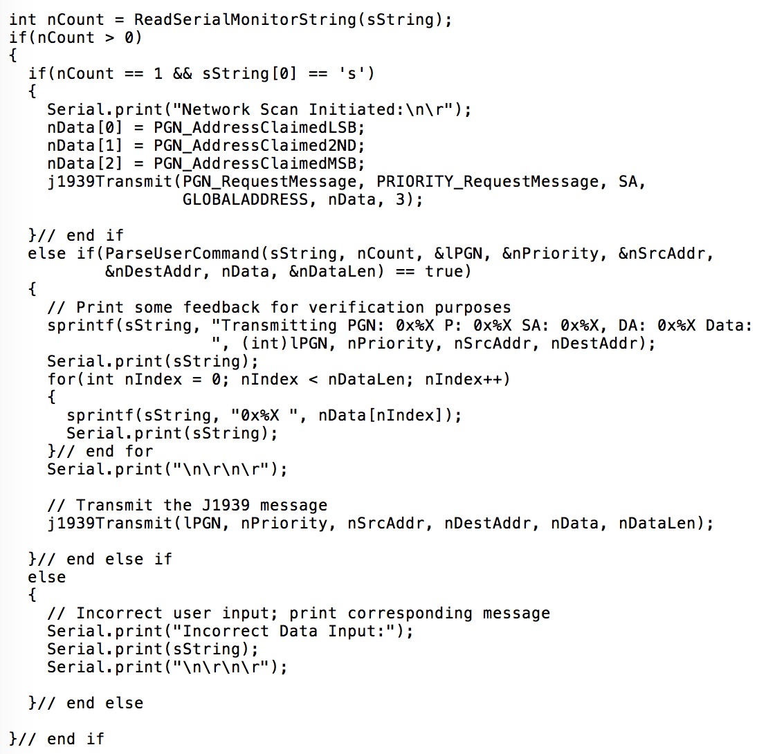
You may notice a new function called ParseUserCommand, which analyzes the user input and returns the result (true = correct, false = incorrect). When the input was found correct, the function returns the PGN, Priority, Source Address (SA), Destination Address (DA), and the actual data.
As a feedback and reference to the user, the J1939 message is printed on the serial monitor and then being transmitted into the J1939 network.
The following screen shot shows the serial monitor, and, as a proof of concept, I had entered two messages.
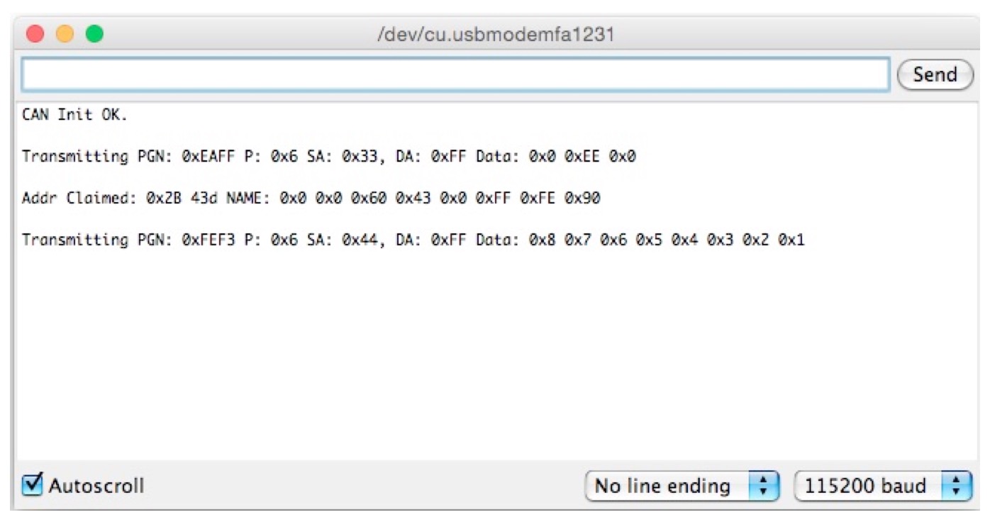
The first message is the Request for Address Claimed message, and therefore the serial monitor shows the reaction from the network (Node address 0x2B). The second message is the Vehicle Position message (PGN 65267 = 0xFEF3), which we had used in a previous example (See chapter SAE J1939 Simulation Example).
The following screen shot from the ADFweb CAN Bus analyzer software confirms the functionality:
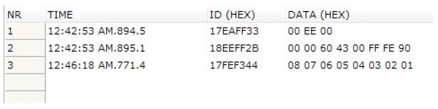
- Line 1: The Arduino sends the Request for Address Claimed message.
- Line 2: The SAE J1939 node at address 0x2B responds with the Address Claimed message.
- Line 3: The Arduino sends the Vehicle Position message (PGN 65267).
As I mentioned before, while this project is only a simple example, there are numerous possibilities to extend the code to a professional SAE J1939 solution. However, one important part of an SAE J1939 to USB gateway is the visualization of received and transmitted data. The following code will give you the basis for accomplishing a professional graphical user interface under Windows.

SAE J1939 has become the accepted industry standard and the vehicle network technology of choice for off-highway machines in applications such as construction, material handling, and forestry machines. J1939 is a higher-layer protocol based on Controller Area Network (CAN). It provides serial data communications between microprocessor systems (also called Electronic Control Units - ECU) in any kind of heavy duty vehicles. The messages exchanged between these units can be data such as vehicle road speed, torque control message from the transmission to the engine, oil temperature, and many more.
A Comprehensible Guide to J1939 is the first work on J1939 besides the SAE J1939 standards collection. It provides profound information on the J1939 message format and network management combined with a high level of readability.