Recent Posts
SAE J1939 Monitor Software - Setting Up PGN Simulation Such As Engine Coolant Temperature
Posted by on
In this post, I will explain the setup of SAE J1939 PGN simulation with our JCOM1939 Monitor software, and I will use the Engine Coolant Temperature as a randomly chosen example. Let me emphasize the point that you can set up any PGN with our software. However, please be also aware that you will need the SAE J1939-71 Standard (available as a download, currently priced at US$81) as a reference, as it documents all standardized PGNs, their data format, and transmission frequency.
A few notes before we look into the details:
- Our JCOM1939 Monitor software works only in combination with one of our SAE J1939 monitor and simulation devices, such as:
- For more detailed information on the JCOM1939 Monitor program, see the online manual.
- Most importantly, please be aware that you will need at least a second SAE J1939 node to establish a network. If you don't have access to a second node, have a look at our SAE J1939 Starter Kit.
PGN 65262 Engine Temperature 1
According to the SAE J1939-71 Standard, the Engine Coolant Temperature is part of PGN 65262; it is the first byte in the 8-Byte data field as defined by SPN 110. SAE J1939-71 also states that the data is transmitted using a one-second interval.
SPN 110 explains the coolant temperature format:
- Length = 1 Byte
- The format is one degree Celsius per bit, with a -40 degree C offset.
- The temperature range is from -40C (-40F - 0x00) to +215C (419F - 0xFF).
SPN 110 - Engine Coolant Temperature Setup
In the following, we are using our SAE J1939 ECU Simulator Board with USB Port, however, the choice of hardware has no impact on the setup process.
As shown in the following image, the device connects per the COM3 port to the software (this is the default but may be different on your computer).
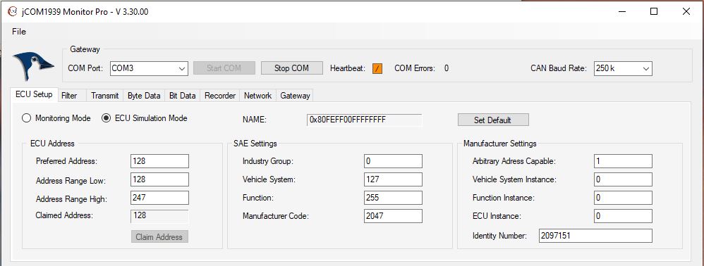
In order to set up and transmit any PGN, we need to assign a node address to the simulator. In all consequence, you should also set up the NAME of the device, but in our example, we go with the default settings. In regard toi the node address, we'll go with the default address, too, which is 128.
Note: The node address range range allows the simulator to find an address other than 128, in case that 128 is already taken in the network. If a new address was determined, it will be reported back to the JCOM1939 software.
Now, in order to start the address negotiating process, you need to engage the ECU Simulation Mode as shown in the image and click on the Claim Address command button. The JCOM1939 Monitor program will display the valid node address.
In reference, see the raw CAN Bus data frame for claiming node address 128:

In the Transmit section of the JCOM1939 software, set up PGN 65262 as shown in below image. In our example, I have set up byte #1 as 0xFF, representing the coolant temperature; the remaining data are set to 0x00 just to separate them visibly.
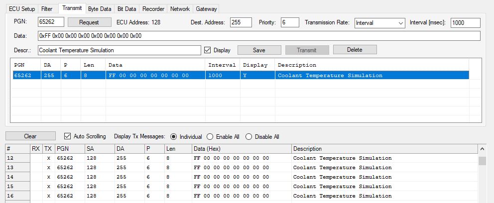
When you click the Save command button, the device will start the data transmission. For a reference, see also the raw CAN Bus data:
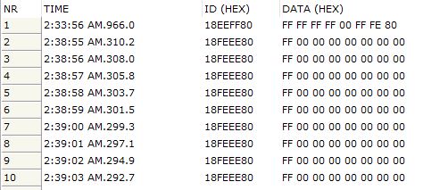
Engine Coolant Temperature - Simulation
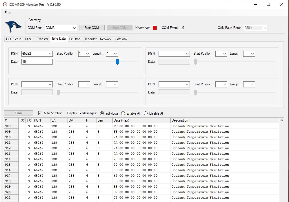
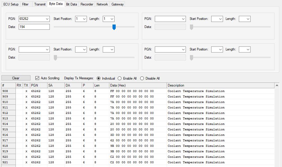
There are two ways of simulating the engine coolant temperature: 1. Through editing the data string or 2. Using a slider as provided by the JCOM1939 software. I chose the slider, because it is by far more exciting to use.
In the JCOM1939 software, switch over to the Byte Data section, select PGN 65262, set Start Position to 1 and Length to 1 as shown in the image below. Now move the corresponding slider and watch the data change:
Last, but not least, here is the raw CAN Bus data:
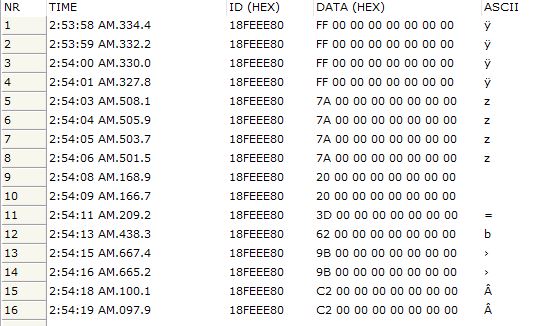
And yet again, you can set up any PGN and simulate any data associated with that PGN by using the slider (analog data) or switch to the Bit Data section to simulate digital I/O signals.
A Comprehensible Guide to J1939
SAE J1939 has become the accepted industry standard and the vehicle network technology of choice for off-highway machines in applications such as construction, material handling, and forestry machines. J1939 is a higher-layer protocol based on Controller Area Network (CAN Bus).
It provides serial data communications between microprocessor systems (also called Electronic Control Units - ECU) in any kind of heavy duty vehicles. The messages exchanged between these units can be data such as vehicle road speed, torque control message from the transmission to the engine, oil temperature, and many more.
The information in this book is based on two documents of the SAE J1939 Standards Collection: J1939/21 - Data Link Layer J1939/81 - Network Management A Comprehensible Guide to J1939 is the first work on J1939 besides the SAE J1939 standards collection.
It provides profound information on the J1939 message format and network management combined with a high level of readability.
 Loading... Please wait...

