Recent Posts
SAE J1939 Data Stream Recording With Raspberry Pi
Posted by on
 The Raspberry Pi is undoubtedly the perfect embedded system to read and record data streams from a vehicle bus. The Linux operating system provides the means of an established file management system, and these days there are multiple choices for the appropriate RPi CAN or SAE J1939 hardware interface.
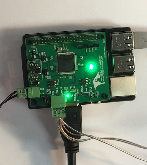
In the following project, I am using the Copperhill SAE J1939 Turbo Interface for Raspberry Pi (jCOM.J1939.RPi) to read and record an SAE J1939 data stream.
My ultimate goal was to create a small-sized embedded solution. For that purpose I used the full-sized Raspberry Pi 3 during the development phase, while the final product will involve the Raspberry Pi Zero.
The SAE J1939 Interface
The board incorporates an ARM processor with CAN transceiver for use on the Raspberry Pi while allowing the operation with any other RPi-compatible board. The jCOM.J1939.RPi integrates an 100 MHz ARM Cortex-M3 with a CAN transceiver and a fast serial connection to the Raspberry Pi. The processor, acting as an SAE J1939 gateway, receives and processes all J1939 data frames, including filtering of PGNs, thus reducing the processing burden on the RPi CPU. The processor also manages all timing requirements according to the SAE J1939 standards, which eliminates any impact on protocol performance due to high RPi CPU loads.
The processed data delivered to the application includes the PGN, data, and priority. Any data length, either the standard 8 bytes or up to 1785 bytes (TP = Transport Protocol) are supported, freeing the application engineer from managing tedious protocol features.
The jCOM.J1939.RPi allows the Raspberry Pi to run your J1939 application comfortably even at high bus load, without slowing down your application responses.
In order to more efficiently serve automotive applications, the jCOM.J1939.RPi board supports an optional extended input power range of 7 to 36 VDC to power the entire system, i.e. including the RPi itself.
The Test Conditions
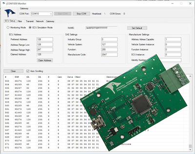
In order to simulate the SAE J1939 data stream, I used our SAE J1939 ECU Simulator Board with USB port in combination with the jCOM1939 Monitor software for Windows.
The jCOM1939 Monitor Software is the perfect tool to monitor, analyze, and simulate SAE J1939 data traffic. The system combines our jCOM.J1939.USB that functions as an SAE J1939 to USB (or UART) gateway.
The comprehensive and easy-to-use, easy-to-understand Windows software displays not only SAE J1939 data traffic; it also allows to scan the network, simulate an ECU (incl. full node address negotiation features), and respond to data request messages.
The Recording Software
Important!
The following description refers to the initial release and the actual code may change over time due to firmware updates. The basic functionality is still the same, but please refer to the jCOM.J1939.RPi product page and read the information regarding firmware updates.
I used the C program as described in our post "C" Programming The SAE J1939 Turbo Interface for Raspberry Pi as a basis and added the recording features to it.

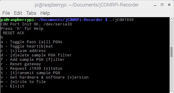
I added the "w" command as shown in the above help screen and also added a timestamp to the received J1939 data frame printout. I will not go into all programming aspects, but most of the changes are in the main.c file, while the filename for the recorded messages is defined in config.h.
Please be aware that all recording features still have room for improvements. Specifically, I did not add code to check errors while writing to the file.
In order to compile the program, run the following command in terminal mode:
gcc main.c COM1939.c CANInterface.c -o jCOM1939
Naturally, you can use any other name than jCOM1939 for the executable file.
To run the program, type:
./jCOM1939
Recording the SAE J1939 Data Stream
First of all, for mere monitoring of J1939 data, you do not need to claim a node address, even though it is supported by the RPi interface. To display all SAE J1939 messages from the vehicle bus, simply type "a", and you will see the screen print. In order to record the messages, type "w". The screen print will cease until you hit "w" again.
The file name I used is "jCOMRecord.txt", and that can be changed easily in the config.h file. Please be aware that any new recording session will overwrite any previous file. As I mentioned, the software leaves ample room for extensions, and my intention was only the proof of concept.

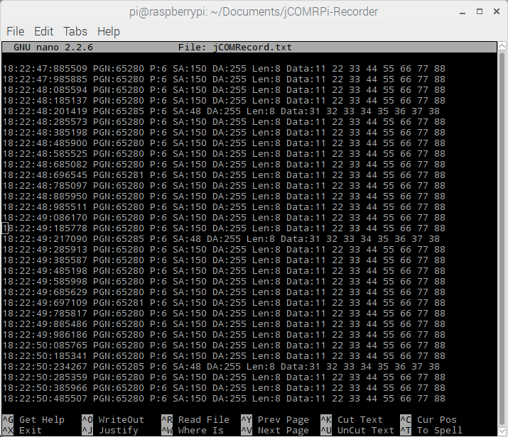
The above image shows the J1939 data stream as produced by our J1939 ECU Simulator board and recorded by the C program.
The timestamp information shows the time in hours (0...23), minutes, seconds, and micro-seconds. A resolution in milliseconds would not be sufficient, since a regular J1939 data frame takes less than 1 millisecond to transmit at 250 kbps.
Note: We are working on adding 500 kbps to the RPi SAE J1939 interface firmware. Actually, this will be an automatic CAN baud rate detection according to SAE J1939/16.
The following information is the same as in the original code: PGN, Priority, source address, destination address, data length, and the actual data.
Note: Any PGN with more than the standard 8 bytes will be displayed entirely in the same format, meaning you don't need to deal with segmented data frames. All this is accomplished automatically by the interface firmware.
Download the C Source Code
All sample programs and other code samples and projects as introduced on this website are free software; you can redistribute and/or modify them. The programs are introduced in the hope that they will be useful, but WITHOUT ANY WARRANTY; without even the implied warranty of MERCHANTABILITY or FITNESS FOR A PARTICULAR PURPOSE. With downloading any of these programs, you confirm that these code samples and projects were created for demonstration and educational purpose only.
Using the Raspberry Pi Zero

As I mentioned previously, my goal was to create a small-sized embedded solution that fits easily into a small enclosure. While I do like the Raspberry Pi 3 and its capabilities, I am quite fascinated by the small form factor of the Raspberry Pi Zero, which, in my personal opinion, is a better choice when you don't need multiple USB ports and/or Ethernet. That is definitely the case for this project.
This image to the left shows the Raspberry Pi Zero mounted on top of the RPi SAE J1939 interface in order to assure proper access to the USB and HDMI connectors. The system fits perfectly into a 3.75" (W) x 4" (L) x 1.25" (H) enclosure and still leaves room for external connections.
The idea is to use either an open-ended SAE J1939 cable or provide a DB9 connection for an SAE J1939 to DB9 cable.
 Loading... Please wait...

