 Loading... Please wait...
Recent Posts
SAE J13939 Data Recorder With Raspberry Pi Zero
Posted by on

Our jCOM.J1939.USB gateway board is a vehicle network adapter for SAE J1939 applications, which allows any host device with a USB COM port to monitor SAE J1939 data traffic and communicate with the SAE J1939 vehicle network.
The board supports the complete SAE J1939 protocol according to SAE J1939/81 Network Management (Address Claiming) and SAE J1939/21 Transport Protocol (TP). It comes with an extensive programming interface for the Raspberry Pi, including full C source code for short time-to-market developments. In this case, we have chosen the Raspberry Pi Zero due to its small form factor. Needless to mention, but, of course, the following will also work with any other version of the Raspberry Pi.
The strength of the USB gateway lies in the fact that the entire SAE J1939 protocol, including all timing requirements, is stored on-chip, thus not only taking the burden off the RPi CPU but also circumventing the need for addressing critical timing requirements. The board uses a USB COM port to communicate with the RPi, i.e., all data transfer is managed through standard COM port access (/dev/ttyUSB0). The communication protocol between the board and the primary system (e.g., a PC, Raspberry Pi, or any other Linux system) is well documented, which allows a smooth portation to any computer system with a USB connection. A working source code library exists for the Raspberry Pi (C using the standard GCC compiler).
With all its features, the USB gateway enables the simulation of an SAE J1939 ECU (Electronic Control Unit), as well as monitoring and storing received data frames.
Why Not Implement a Linux SAE J1939 Protocol Stack?
There are only very few choices in the marketplace for purchasing an SAE J1939 protocol stack, and the pricing is prohibitive compared to the RPi's low-cost approach. The cost range is within several thousands of dollars, and the use is limited due to license agreements.
We had considered an implementation of an SAE J1939 protocol stack for Linux (for instance on the Raspberry Pi in combination with our PiCAN boards) but always come to the same conclusion: The actual implementation may be smooth, but the actual problem is warranting reliable operation, specifically satisfying the various SAE J1939 timing requirements.
Yet again, it is possible, but the programming efforts would be immense. Add to this the ever-changing operating system updates and the work proving that the current protocol stack will still work with each new Linux version (not even talking about backward-compatibility).
In contrast, communication with our USB board is completely operating-system-independent and thus immune to frequent Linux updates. The SAE J1939 functionality remains consistent, and the protocol stack's performance is not impacted by the operating system.
Connecting the jCOM.J1939.USB Board
Connect the USB board to any free USB port on your Raspberry Pi. The Raspbian operating system will identify the new USB connection automatically; thus there is no driver installation needed.

For the CAN/J1939 connection, the board uses a 5-pin terminal connector. The board also features an internal termination resistor of 120 Ohm, which is activated per wire jumper in the terminal block.
The connections (from top to bottom) are:
- CAN_H
- CAN Termination Wire Jumper
- CAN Termination Wire Jumper
- CAN_L
- GND
Important!
It sounds obvious, but it is, nevertheless, overseen frequently: You will need a second SAE J1939 node (or a whole network) to control the board's complete functionality. The board comes with a "heartbeat" function (i.e., a heartbeat message sent per USB every one second), indicating that the board is "awake" and running, but that doesn't prove any SAE J1939 functionality.
On-Board LEDs
The jCOM.J1939.USB board comes with three LEDs:
- PWR - Directly connected to power.
- LED2 - Indicates USB port activity (including heartbeat message)
- LED1 - CAN / SAE J1939 activity
Upon powering up the board you will see the power LED plus the USB LED blinking with a one second frequency (heartbeat).
Programming the jCOM.J1939.USB Using C
The jCOM.J1939.USB C source code contains of the following files:
- main.c
- config.h
- COM1939.c
- COM1939.h
- CANInterface.c
- CANInterface.c
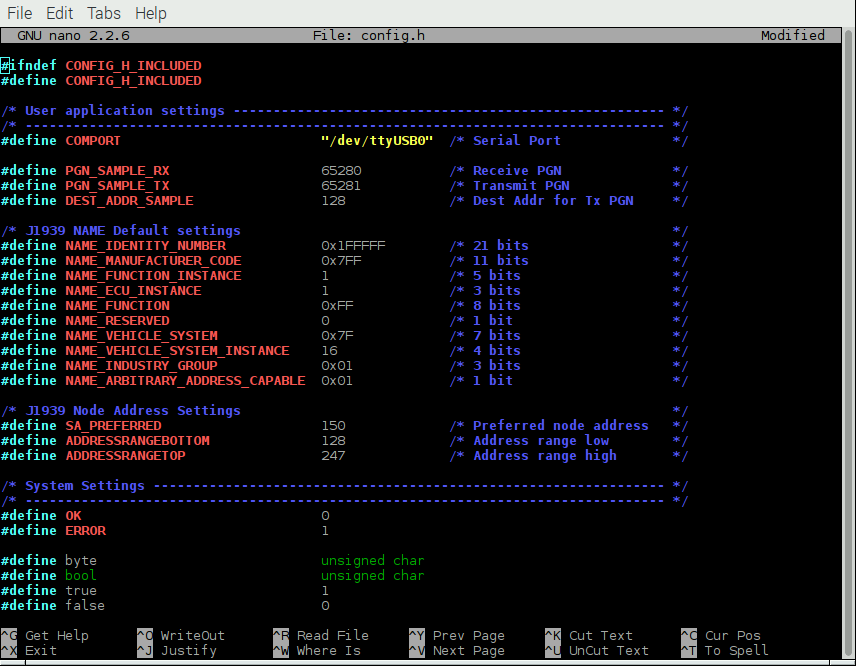
The config.h file is important, because it allows some user/application settings such as:
- Preferred Node Address (for Address Claim Process)
- Negotiable Node Address Range (also for Address Claim Process)
- ECU NAME
The COM1939 and CANInterface modules manage the communication between the Raspberry Pi and the jCOM.J1939.USB board. These modules need no further detailed attention, unless you want to spend the time to understand and extend them.
The most important module, when it comes to mere application programming, is main.c.
To initialize the board, use the following lines:
strcpy(sCOMPort, COMPORT);
COM1939_Initialize(&sCOMPort[0]);
COM1939_SendMessageMode(MSGMODE_GATEWAY2);
In order to call the SAE J1939 protocol stack, you need only one line:
int nStatus = COM1939_Receive(&lPGN, &nPriority, &nSourceAddress, &nDestAddress, &nData[0], &nDataLen);
This function call receives messages from the J1939 network. However, before you can receive any messages, you will need to set message filters for the PGNs you need:
COM1939_AddFilter(PGN_SAMPLE_RX);
PGN_SAMPLE_RX is defined in config.h and it can be replaced with any PGN. And, of course, you can add more PGNs using the same function call (up to 80 PGNs).
To negotiate an address, use this line:
COM1939_SetProtocolParameters(msgNAME, SA_PREFERRED, ADDRESSRANGEBOTTOM, ADDRESSRANGETOP, OPMODE_EVENT, true);
Again, all parameters are set in config.h.
Please, be aware that you need a valid J1939 node address before you can transmit data into the network. To transmit data, use the following line:
COM1939_Transmit(6, PGN_SAMPLE_TX, nSA, DEST_ADDR_SAMPLE, &SampleTxData[0], 8);
For further details, have a closer look at the main.c file. The code explains all functionality is an easy-to-comprehend form.
Compile and Run the C Program
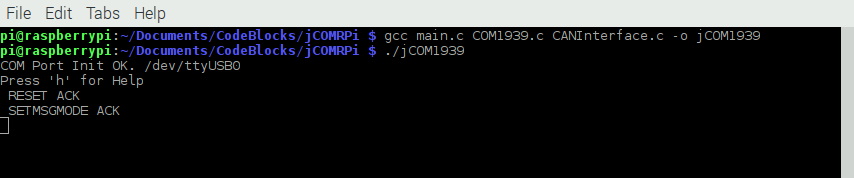
In order to compile the program, run the following command in terminal mode:
gcc main.c COM1939.c CANInterface.c -o jCOM1939
Naturally, you can use any other name than jCOM1939 for the executable file.
To run the program, type:
./jCOM1939
Further Information
Download the C Source Code
Note: While not explicitly mentioned in the following, the program also allows the recording of SAE J1939 data frames, i.e. writing the data to a file (We added the functionality after this post was written).
Some Screen Shots
To edit or view any of the program modules use the internal editor, for instance:
nano config.h
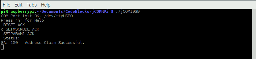
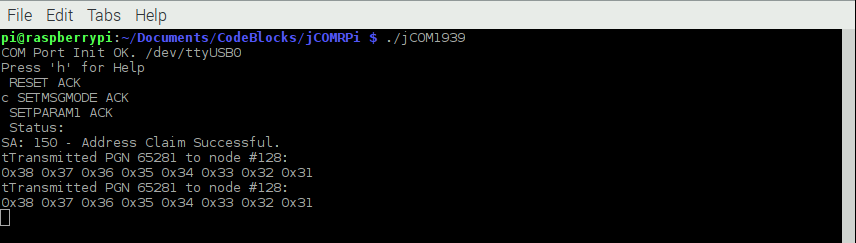
After executing the jCOM1939 program, the screen will show the COM port status, either successful (as shown here) or with an error message:
Type 'h' for help:
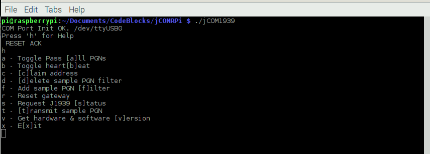
Type 'b' to check the reception of the heartbeat message:

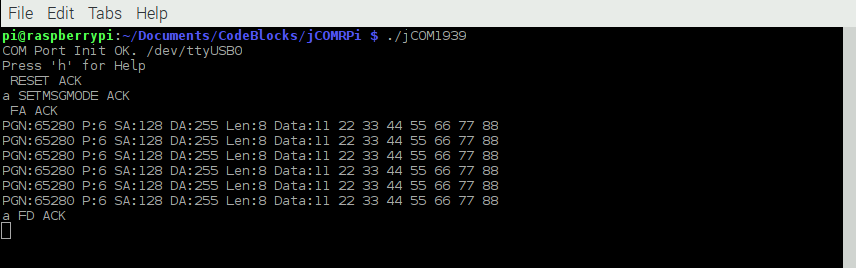
Type 'f' to apply the message filter, type 'd' to delete the message filter:
Type 'c' to initiate the address claim process:
Type 't' to transmit a J1939 data frame:
Last, but the hardware configuration provides ample opportunities for implementing further applications that we haven't attempted yet but are definitely feasible:
- SAE J1939 to WiFi Gateway
- SAE J1939 to Bluetooth Gateway
- SAE J1939 to Ethernet Gateway

Exploring Raspberry Pi: Interfacing to the Real World with Embedded Linux
This book promotes engineering principles over a 'recipe' approach to provide you the experiences you need to create and build your projects. You will learn the basic principles in a way that transfers to any electronics, electronic modules, or external peripherals, using a "learning by doing" approach that caters to beginners and experts.
The book starts with elementary Linux and programming skills and helps you stock your inventory with common parts and supplies. Next, you will discover how to produce parts work together to accomplish the goals of the project, no matter what type of components you use.
The companion website provides a full repository that structures all of the code and scripts, along with links to video tutorials and supplementary content that takes you deeper into your project.