 Loading... Please wait...
Recent Posts
PiCAN FD Functionality Test - CAN Bus FD Duo Board with Real Time Clock for Raspberry Pi
Posted by on
CAN FD (CAN with Flexible Data-Rate) is an updated version of the CAN 2.0B protocol. It takes into account the requirement of the automotive industry to make Classical CAN faster. To achieve that, two principles have been introduced:
- Faster transfer of the data frame
– the Arbitration Field (ID and Acknowledgement) remain unchanged so that the arbitration remains robust - More databytes in a data frame
– The classic CAN frame contains 0 to 8 data bytes. The CAN FD frame contains 0 to 64 data bytes
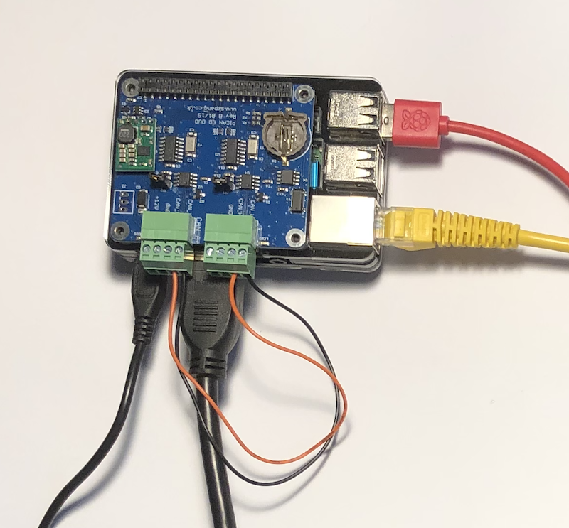
Our PICAN FD - CAN Bus FD Duo Board with Real-Time Clock for Raspberry Pi provides two-channel CAN-Bus FD capability for the Raspberry Pi. It uses the Microchip MCP2517FD CAN controller with MCP2562FD CAN transceiver. Connections are made via a 4-way screw terminal. A real-time clock with battery backup (battery not included) is also on the board.
The advanced CAN FD bitrate extends the length of the data section to up to 64 bytes per frame and a data rate of up to 8 Mbps.
The DUO version of the CAN FD Raspberry Pi HAT also provides perfect conditions for a functionality test with the need of utilizing an industry-grade CAN FD analyzer hardware and software.

Note: Despite the previous statement, I highly recommend the use of a CAN FD gateway with Windows analyzer software. While the above introduced DUO CAN FD board provides an easy and inexpensive method of testing the board's functionality, you may still run into technical problems down the road, i.e. when it comes to more complex applications.
Many beginners deal with a number of unknowns (such as CAN FD, the Raspberry Pi hardware, the Linux operating system, the sample programs, and more), which may lead to misinterpretations of the actual problem. That, in turn, results in development delays, not to mention frustration with the setup.
CAN FD adapters with Windows monitoring and analyzing software are designed to soberly display the CAN FD data traffic without the ifs and whens of your own software.
Let me stress the point that the PICAN series of CAN Bus interfaces for the Raspberry Pi has an excellent track record in regard to hardware and software reliability, and most of our efforts for technical support are based on helping customers understand the technology.
For our tests, we are using the PEAK System CAN USB PRO FD Adapter, which also comes with a LIN Bus channel. If your development efforts do not include LIN Bus, we recommend the PEAK CAN USB FD Adapter (as shown in the image).
The functionality test is divided into two sections, the software and the hardware setup. I accomplished the software setup by following the instructions in the user manual to the point (which is actually an important point; most of the technical "problems" reported to us result from not reading the manual). I will not repeat the user manual's content in this post, but I would like to mention the (downloadable) CAN utilities, which include the cansend and candump applications. They play a vital part in the functionality test.
The hardware setup includes (besides the actual board installation) soldering two jumpers for the termination resistors. The CAN Bus standard requires to connect a termination resistor of 120 Ohm at "each end of the network." In our case, both ends are on the board. Consequently, we need to close both jumpers.
In a next step, I connected the CAN ports with each other (CAN_H to CAN_H and CAN_L to CAN_L, as shown in the above image).
In order to initialize both CAN Bus ports, open the terminal (command line) window and type the following:
sudo /sbin/ip link set can0 up type can bitrate 500000
sudo /sbin/ip link set can1 up type can bitrate 500000
This initializes both ports for Classical CAN operation only (the bitrate was chosen randomly; any standard rate will work).
To initialize the CAN ports to support CAN FD, type the following:
sudo /sbin/ip link set can0 up type can bitrate 500000 dbitrate 2000000 fd on sample-point .8 dsample-point .8
sudo /sbin/ip link set can1 up type can bitrate 500000 dbitrate 2000000 fd on sample-point .8 dsample-point .8
Note: The above example uses a CAN FD bitrate of 2 Mbps, which you can increase up to 8 Mbps, but please be aware that you can't enter a fraction of Mbps (such as 6.2 Mbps, which I did, and it didn't work). The onboard CAN FD controller's clock divide register requires whole numbers.
As demonstrated in the screenshot below, I used CAN0 to send messages (cansend), while CAN1 is the receiver (candump).

First, I transmitted a Classical CAN Bus data frame (Note the single "#"; message ID and data are randomly chosen):

Then, I transmitted a CAN FD data frame (Note the "##") with BSR and one without BSR.
The following image shows the result on CAN1:

Naturally, you can send data in both directions. For more information on our CAN FD boards, see https://copperhilltech.com/can-fd-interfaces/.

Teensy 4.1 Triple CAN Bus Board with 240x240 LCD and Ethernet
This is a Teensy 4.1 board with triple CAN connections, two CAN 2.0B and one CAN FD, and ethernet magjack. It can be powered by an external +12 VDC with reverse voltage protection. Included is also a 240x240 wide angle IPS TFT LCD display.
The Teensy 4.1 is an Arduino-compatible board with an Arm Cortex-M7 microcontroller running at 600 MHz. The board is compatible with the Arduino IDE and the Arduino library. In most cases, code written for another Arduino board works with a minimum of changes on a Teensy. As the name implies, the board is tiny. For example, the current form factor is only about 18 by 36 millimeters. However, do not let the size mislead you; these boards pack a ton of functionality. For example, the new Teensy 4.1 features a megabyte of RAM, two megabytes of Flash, a bevy of I/O options, cryptographic support, a hardware floating-point processor (FPU), and a built-in real-time clock (RTC).