Recent Posts
Guide To SAE J1939 - J1939 Characteristics
Posted by on
The following is an excerpt from A Comprehensible Guide To J1939 by Wilfried Voss.
SAE J1939 is a higher-layer protocol based on Controller Area Network (CAN). It provides serial data communications between microprocessor systems (also called Electronic Control Units - ECU) in any kind of heavy-duty vehicles.
Everything that has to do with CAN is based on maximum reliability with the maximum possible performance in mind, not only in regards to required electrical robustness, but also due to high speed requirements for a serial communication system.
While the CAN Bus itself is sufficiently suited for communication in a regular automobile or in small industrial applications, it comes with a few shortcomings in regards to network management. In order to add these features CAN as the physical layer (the entire CAN Bus protocol is on silicon) can be extended by additional software, the so-called higher layer protocols (such as J1939).
J1939 takes advantage of CAN features such as:
- Maximum reliability
- Excellent error detection & fault confinement
- Collision-free bus arbitration
Other than CAN, which supports up to 1 Mbit/sec, J1939 limits itself to 250 kbit/sec. CAN was designed to be as close to real-time applications as possible. This level of performance is not required for J1939.
Note: It was somewhat disconcerting to learn that the SAE J1939 standard has no problem with compromising the CAN Bus standard. The Network Management (SAE J1939/81), for instance, allows scenarios where two CAN nodes with the same message ID can access the bus. The result of such a situation is unpredictable. In addition, the SAE J1939 message format (as described in SAE J1939/21) does not take advantage of the message filtering as provided by all CAN controllers in the industry.
SAE J1939 Quick Reference
- Higher-Layer Protocol using CAN as the physical layer
- Shielded twisted pair wire
- Max. network length of 40 meters (~120 ft.)
- Standard baud rate of 250 kBit/sec
- Max. 30 nodes (ECUs) in a network
- Max. 253 controller applications (CA) where one ECU can manage several CAs
- Peer-to-peer and broadcast communication
- Support for message length up to 1785 bytes
- Definition of Parameter Groups (Predefined vehicle parameters)
- Network Management[1] (includes address claiming procedure.
It must be emphasized that the maximum network length of 40 m (roughly 120 ft.), the baud rate of 250 kBit/sec and the maximum number of nodes (30) are self-inflicted restrictions by the SAE, most probably with the intention to keep everything on the extreme safe side and thus trying to prevent potential runtime problems.
In all consequence, the network length at 250 kBit/sec, according to ISO 11898, is 250 m (roughly 750 ft.).
There is no reason to believe that J1939 cannot be operated at the max. CAN baud rate of 1 MBit/sec. Naturally, the network length would drop, but the mere J1939 protocol features post no restriction in regards to the baud rate.
The J1939 protocol utilizes an 8 bit device (ECU) address, which would allow the operation of 256 nodes in the same network. It can only be assumed that the SAE was trying to keep the bus traffic on a low level by restricting the maximum number of nodes to 30. Elaborating comments on this restrictions may be embedded somewhere in the standard.
In all consequence, the ECU address is really a Controller Application address in a situation where each ECU may accommodate several Controller Applications. The 253 addresses (Address 254 is reserved for Network Management, Address 255 is used for global addressing, i.e. message broadcasting) are assigned (claimed) for the Controller Applications, not the actual ECU.
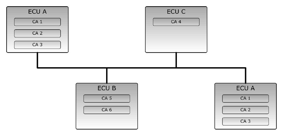
The following picture shows an example, where, for instance, ECU A accommodates three controller applications.

The picture also demonstrates that ECUs of the same function (ECU A) can co-exist in a J1939 network without address collision. J1939 features a very ingenious feature, the Address Claim procedure which automatically assigns addresses to each Controller Application. In case of an Address Claim conflict, the Controller Applications are able to claim another free address.
The main characteristic of J1939 is, however, the use of Suspect Parameter Numbers (SPN) and Parameter Group Numbers (PGN) which point to a huge set of predefined vehicle data and control functions. The definition of PGNs and Suspect Parameter Numbers (SPN) make out the bulk of the SAE J1939 Standards Collection. SPNs define the data type and use for each parameter in a parameter group. The Parameter Group Number is embedded in the 29-Bit CAN message identifier.
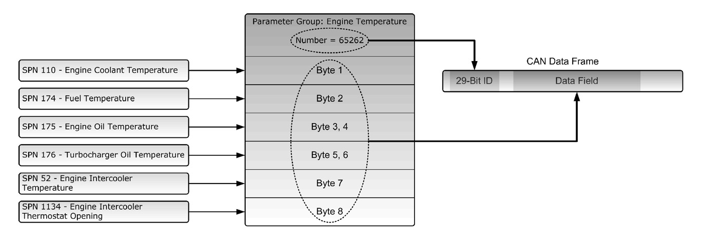
The following picture demonstrates the use of Suspect Parameter Numbers, Parameter Groups and Parameter Group Numbers.

The Suspect Parameter Numbers in this example point to vehicle data associated with the Engine Temperature. Note that all SPNs have been selected logically to fit into the Parameter Group Engine Temperature.
The Parameter Group Engine Temperature has been assigned the Parameter Group Number (PGN) 65262. It is in fact the Parameter Group Number (embedded in the 29-Bit message ID) plus the actual data (embedded in the CAN data field) that is being transmitted into the CAN bus.
It is a requirement that all nodes sending or receiving the PGN 65262 know the structure of the PGN as well as all associated SPNs.
[1] The SAE J1939 Network Management does not include support for a Master/Slave configuration and it does not include node monitoring. These functions can nevertheless be implemented on an application level.
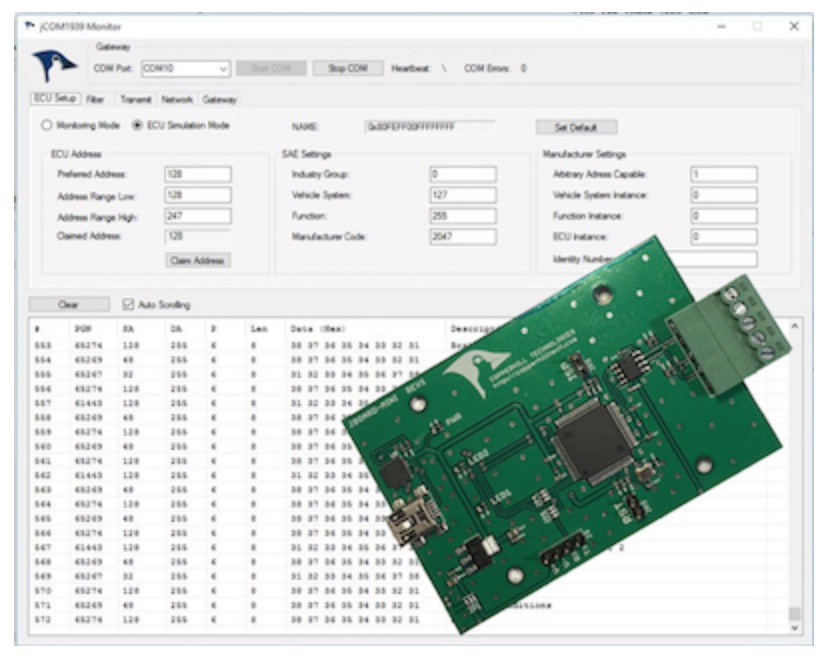
SAE J1939 ECU Simulator Board With USB Port
The jCOM.J1939.USB gateway board is a high-performance, low-latency vehicle network adapter for SAE J1939 applications. It allows any host device with a USB COM port to monitor SAE J1939 data traffic and communicate with the SAE J1939 vehicle network.
The board supports the full SAE J1939 protocol according to J1939/81 Network Management (Address Claiming) and J1939/21 Transport Protocol (TP). It is also supported by an extensive programming interface for Windows and Linux/Ubuntu applications, including full C/C++/C# source code for short time-to-market developments.
The strength of the board lies in the fact that the entire SAE J1939 protocol, including all timing requirements, is stored on-chip, thus taking the burden off the main system. The board uses a USB COM port to communicate with the main system, i.e. all data transfer is handled through a standard COM port access.
The communication protocol between the board and the main system is well documented and thus allows a porting to any computer system with a USB connection. Working source code libraries exist for Windows (C# under Visual Studio 2012/2013), Linux and its derivatives (C++ using Code::Blocks), and Raspberry Pi (C using the standard gcc compiler).
 Loading... Please wait...


