Recent Posts
A Simple SAE J1939 to USB Gateway with the Arduino Uno, Mega 2560, Due, Teensy, ESP32
Posted by on
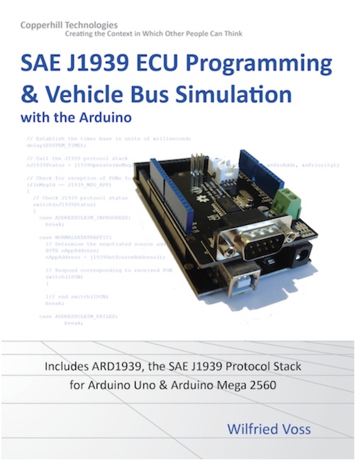
The following is an excerpt from SAE J1939 ECU Programming & Vehicle Bus Simulation with Arduino by Wilfried Voss
I deem it necessary to clarify the definition of “SAE J1939 to USB Gateway” because there are several variants of gateway applications.
If you browse through the Internet in search for SAE J1939 gateways, you will primarily find CAN Bus gateways that support the conversion of 11-Bit and 29-Bit CAN messages into another serial technology such as USB, RS232, etc. Since SAE J1939 is based on CAN Bus messages with a 29-Bit identifier, many manufacturers take the liberty of calling their devices “SAE J1939 gateways,” which is misleading and may lead to technical problems when connecting these devices to an actual vehicle (diesel engine).
The problem lies in the fact that these so-called gateways do not come with an integrated SAE J1939 protocol stack and cannot support the address claiming process, according to SAE J1939/81. When transmitting data into a J1939 vehicle network, you need to supply a node (source) address with the data frame, and that node address must be unique. The absence of a protocol stack in the gateway may result in node ID collisions and may cause serious technical problems.
The problem can be circumvented when all node IDs in the network are hard-coded, and you assign a free node ID to messages you send into the network. This may work in limited cases, but this method is, naturally, not recommended.
The purpose of these types of J1939 gateways should be mere data monitoring, i.e., only receiving J1939 messages (you still need to decipher J1939 messages longer than 8 bytes, which is a cumbersome task). In order to communicate with the vehicle bus (bidirectional communication), you need a full SAE J1939 protocol implementation with address claim procedure and support of messages longer than 8 bytes.
Nevertheless, in the following, I will introduce this kind of gateway with all its disadvantages, but I will do so for mere demonstration and educational purposes. The Arduino sketch, as introduced in the following, is the first step toward a full SAE J1939 gateway with an integrated protocol stack (See chapter ARD1939 – SAE J1939 Protocol Stack for Arduino).
Some of the previous Arduino sketches, as introduced in this book, already provide the features for a simple SAE J1939 to USB gateway. However, they were designed to receive messages. A gateway application requires that we can send messages as well. The need for bidirectional communication also leads to another requirement for a J1939 gateway, namely the definition of a communication protocol between the gateway and the host system (usually a PC).
Since our focus is on the Arduino hardware, the connection between the gateway (i.e., the Arduino) and the PC is established per USB interface. The foundation of the USB protocol is already established through the Serial.print function, and the protocol will be based on transmitting ASCII text.
The data communication is managed through the Arduino’s serial monitor, but I will also introduce a replica of the serial monitor with Visual Studio C# in another chapter to follow. If you wish to create a more sophisticated data communication between the Arduino and a PC, the following projects will provide a solid foundation.
Our simple J1939 to USB gateway will provide three functions:
- A J1939 Network Scanner, i.e., the Arduino will scan a J1939 network for existing nodes and retrieve information from them.
- A Data Traffic Monitor similar to the previously introduced projects.
- A Data Traffic Simulator, i.e. the Arduino will send user-defined messages into the network.
Note: As usual, the following Arduino projects are available through the download page at http://ard1939.com. However, all three functions (network scanner, data traffic monitor, and data traffic simulator) are combined into one project, since the ladder two features are additions to the previous project.
While the code in this book was developed for the Arduino Uno and Mega 2560, we also provide a version for the Arduino Due. We are working on versions for the Teensy, a series of Arduino-compatible embedded modules, and the ESP32, which we will publish in the near future. For the time being, you can download the code and modify/adjust the CAN interface functions to the available hardware.
Arduino-Based ECU Development Board With Dual CAN Bus Interface
Leverage the power of an ARM Cortex M3 32-bit processing capability combined with a dual CAN Bus interface to create your next CAN Bus or SAE J1939 application or prototype. By combining our dual CAN port interface, the Arduino DUE microcontroller, an OBD2 or SAE J1939 cable, and open-source software libraries, you are ready to go with a powerful turn-key Arduino-based dual CAN bus solution.
Use the vast resources of Arduino software (sketches) and hardware components (shields) to create your CAN Bus, OBD2, or SAE J1939 application.
 Loading... Please wait...


