Recent Posts
USB-CAN Analyzer - USB to CAN Bus Serial Protocol Definition
Posted by on
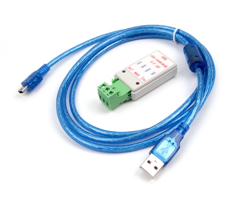
The USB-CAN Analyzer, in combination with the corresponding Windows software, represents a very economical solution to run an effective CAN Bus Analyzer. It allows you to develop, test, manage, and maintain your own CAN Bus network, as well as receiving, sending, logging, and analyzing CAN Bus data.
For the following, we need to point out that the device is manufactured in China, and documentation is sparse. And while this is a very affordable solution, there is naturally room for some improvement. In general, there is no application interface, or, to be more precise, the communication between the USB-CAN device and the host system, in this case a PC running Windows, is not documented. Consequently, there is currently no software support for Linux (e.g. SocketCAN), and it would be useful if users could write their own applications, regardless of the operating system they use.
As a first step in this direction, we invested some efforts to analyze and document the USB communication protocol, which makes it easy developing an application interface.
There has been a document, USB (Serial port) to CAN protocol defines, that was distributed online, claiming a documentation of the "Send and receive data packet format." However, after analyzing the protocol, we believe that the data frame architecture described therein represents the original intention.
We believe that the architecture as described caused problems when it came to higher baud rates, specifically at 1 Mbps in combination with high busloads. Consequently, the firmware developers decided to optimize the data frame size. As a result, they cut the frame size from a static 20 bytes to a dynamic 6 to 16 bytes, depending on message ID length (11 or 29 bits) and number of data bytes.
The following describes the serial protocol as we analyzed it, with a few unknowns remaining. However, the documentation includes all vital information for creating your own CAN Bus application.
CAN Bus Data Frame
The CAN Bus data frame format applies to both, send and receive.
Both message ID lengths, 11-bit standard and 29-bit extended, use the first two bytes in the serial data frame. Depending on the message ID length, the remaining bytes will be filled differently.
The data frame does not utilize a checksum check, most probably due to keeping the number of transmitted bytes to a minimum and cutting down on processing time.
Byte Description
0 0xAA = Packet Start
1 CAN Bus Data Frame Information
Bit 7 Always 1
Bit 6 Always 1
Bit 5 0=STD; 1=EXT
Bit 4 0=Data; 1=Remote
Bit 3…0 Data Length Code (DLC); 0…8
Standard CAN data frame continues:
Byte Description
2 Message ID LSB
3 Message ID MSB
x Data, length depending on DLC
y 0x55 = Packet End
Extended CAN data frame continues:
Byte Description
2 Message ID LSB
3 Message ID 2ND
4 Message ID 3RD
5 Message ID MSB
x Data, length depending on DLC
y 0x55 = Packet End
CAN Bus Data Frame Size
Standard 11-bit 6 bytes with zero data bytes
14 bytes with eight data bytes
Extended 29-bit 8 bytes with zero data bytes
16 bytes with eight data bytes
CAN Bus Initialization Frame
The CAN Bus initialization frame has a constant length of 20 bytes.
Byte(s) Description
0 0xAA = Frame Start Byte 1
1 0x55 = Frame Start Byte 2
2 0x12 = Initialization Message ID
3 CAN Baud Rate (See table below)
4 0x01=STD; 0x02=EXT; Applies only to transmitting
5 – 8 Filter ID; LSB first, MSB last
9 – 12 Mask ID; LSB first, MSB last
13 Operation Mode (See table below)
14 0x01; Purpose Unknown
15 – 18 All 0x00
19 Checksum
Note: The checksum is processed between bytes 2 and 18.
CAN Bus baud rate
0x01 1000k
0x02 800k
0x03 500k
0x04 400k
0x05 250k
0x06 200k
0x07 125k
0x08 100k
0x09 50k
0x0A 20k
0x0B 10k
0x0C 5k
Operation Mode
0x00 Normal
0x01 Loopback
0x02 Silent (Listen-Only)
0x03 Loopback + Silent
CAN Controller Status Frame
The format of the status request and status report frames are identical, where the request frame sends all zeroes between the frame header (frame start tokens plus frame ID) and the checksum, i.e. bytes 3 through 18 are 0x00.
Byte(s) Description
0 0xAA = Frame Start Byte 1
1 0x55 = Frame Start Byte 2
2 0x04 = Status Message ID
3 Receive Error Counter
4 Transmit Error Counter
5 – 18 Unknown Purpose
In case of status report, they may be filled with data
19 Checksum
 Loading... Please wait...

