Recent Posts
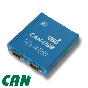
USB Module with 2 CAN FD Interfaces Plus Analog And Digital IRIG-B Inputs
Posted by on
The CAN-USB/400-FD by esd electronics is equipped with two independent CAN FD interfaces according to ISO 11898-1:2015; they are driven by the ISO 16845:2004 certified esdACC (esd advanced CAN Core) implemented in an Altera® FPGA. The interface is able to send and receive ISO conform CAN FD (up to 5 Mbit) or CAN 2.0 A/B messages. The CAN FD bit rate range is validated for the esdACC CAN FD core from 10 kbit/s up to 5 Mbit/s.
Error Injection
Error injection capabilities are a fairly unique feature on standard CAN interfaces (Classical CAN application only). Error Injection provides means to simulate error conditions on CAN bus. Bit patterns can be injected into any living CAN bus. Several trigger conditions and modes are provided.
Software Support
Windows (NTCAN-API) - The CAN layer 2 drivers for Windows are included in the scope of delivery.
The following Higher Layer Protocols are available for the Windows operating system:
Additional free-of-charge esd CAN tools for Windows are downloadable from the esd electronics website. The tools offer efficient setup and analysis of CAN applications and networks.
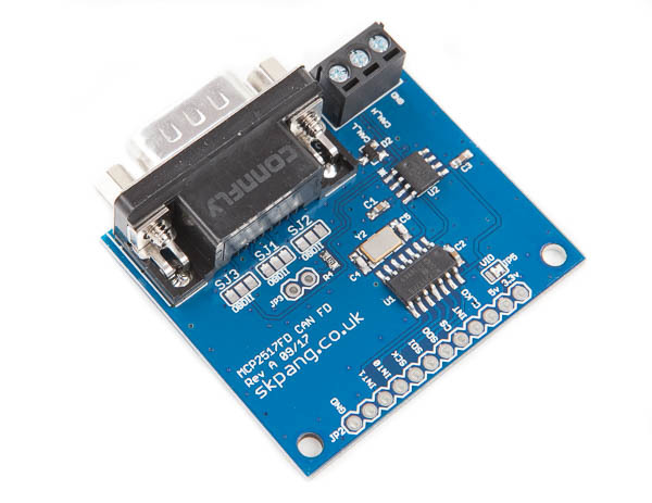
CAN FD Breakout Board With SPI Interface
This CAN FD breakout board utilizes the Microchip MCP2517FD CAN FD controller in combination with the MCP2562FD CAN Bus transceiver.
Features
- Conforms to ISO11898-1:2015
- Supports both CAN 2.0B and CAN FD
- Arbitration Bit Rate up to 1 Mbps
- Data Bit Rate up to 8 Mbps
- Up to 10MHz SPI Clock Speed
- 31 FIFOs configurable as transmit or receive
- 32 Flexible Filter and Mask Objects
- One Transmit Queue
- 32-bit Time Stamp
- Bus Health Diagnostics and Error Counters
- Requires 5v supply with 3.3v or 5v logic
 Loading... Please wait...


